


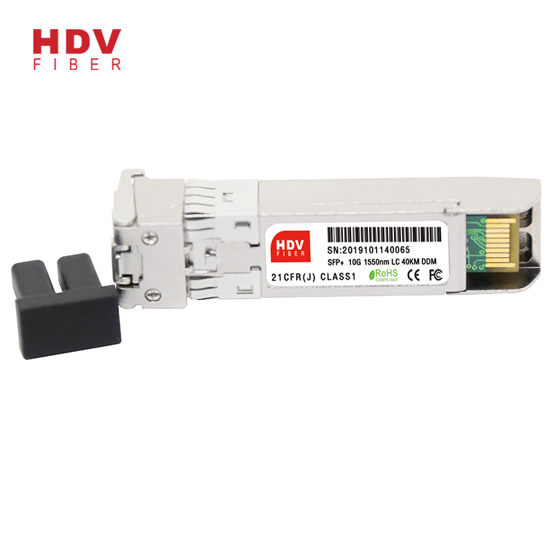
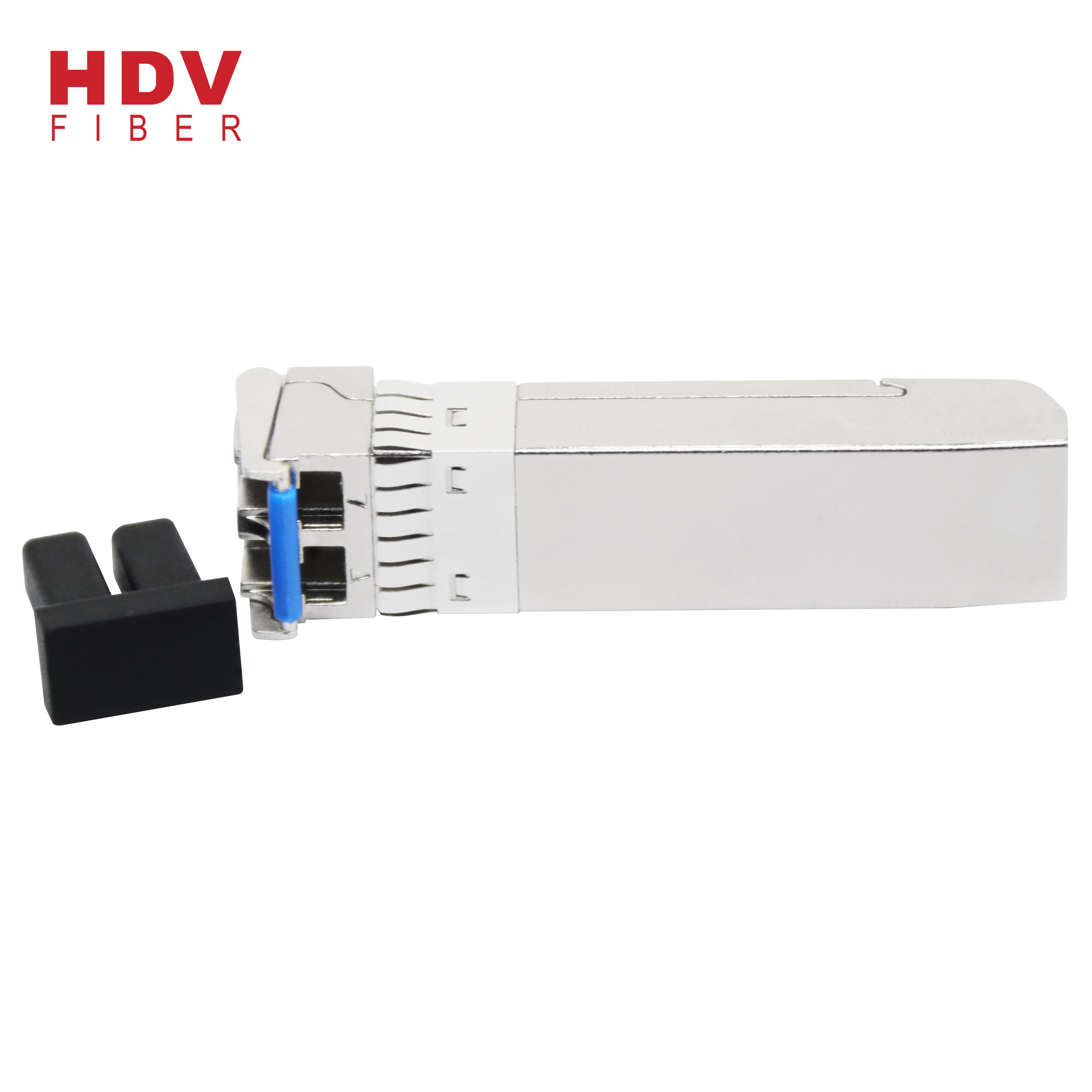
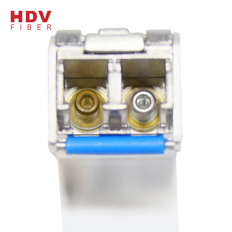
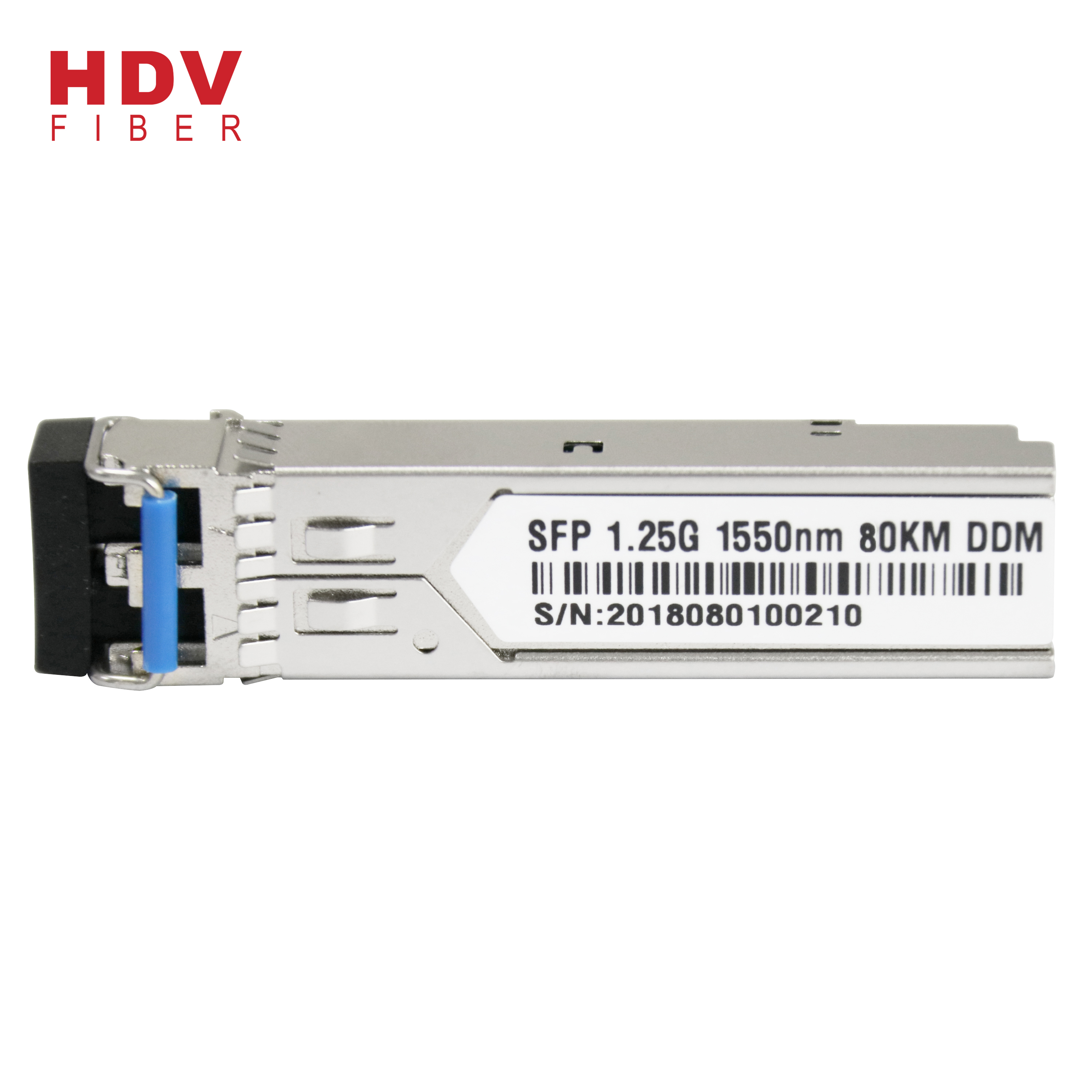
Sfp 10 - 10G 1550nm 40KM LC connector dual fiber optic SFP+ module – HDV Detail:
Application:
- 10GBASE-ER at 10.31Gbps
- 10GBASE-EW at 9.95Gbps
- 8G/10G FC
- Other Optical Link
Product parameters :
|
Part No. |
Wavelength |
Connector |
Temp. |
TX Power (dBm) |
RX Sens (Max.) (dBm) |
Distance |
|
SFP+-10G-ER |
1550EML |
LC |
0~70°C |
-4.7 to 4 |
-15.8 |
40km |
Absolute Maximum Ratings:
|
Parameter |
Symbol |
Min |
Max |
Unit |
|
|
Storage Temperature |
TS |
-40 |
+85 |
℃ |
|
|
Operating Temperature |
TOP |
Commercial level |
-20 |
+70 |
℃ |
|
industrial level |
-40 |
85 |
|||
|
Supply Voltage |
VCC |
-0.5 |
+3.6 |
V |
|
|
Voltage on Any Pin |
VIN |
0 |
VCC |
V |
|
|
Soldering Temperature ,Time |
- |
260℃, 10 S |
℃,S |
||
Operation Environment:
|
Parameter |
Symbol |
Min. |
Typ |
Max. |
Unit |
|
|
Ambient Temperature |
TAMB |
Commercial level |
0 |
- |
70 |
℃ |
|
industrial level |
-40 |
85 |
||||
|
Power Supply Voltage |
V CC-VEE |
3.15 |
3.3 |
3.45 |
V |
|
|
Power Dissipation |
1 |
W |
||||
|
Data Rate |
10GBASE-ER |
10.3125 |
Gbps |
|||
Optical Characteristics:
(Ambient Operating Temperature 0C to +70C, Vcc =3.3 V)
|
Parameter |
Symbol |
Min. |
Typ. |
Max. |
Units |
|||
|
Transmitter Section |
||||||||
| Center Wavelength |
lo |
1480 |
1550 |
1600 |
nm |
|||
| RMS Spectral Width |
Dl |
- |
- |
1 |
nm |
|||
| Side Mode Suppression Ratio |
SMSR |
30 |
dB |
|||||
| Average Output Power |
Po |
-4.7 |
1 |
4 |
dBm |
|||
| Extinction Ratio |
Er |
3.5 |
- |
- |
dB |
|||
| Side Mode Suppression Ratio |
SMSR |
30 |
dB |
|||||
| Dispersion Penalty |
2 |
dB |
||||||
| Input Differential Impedance |
Zin |
90 |
100 |
110 |
Ω |
|||
| Relative Intensity Noise |
RIN12OMA |
-128 |
dB/Hz |
|||||
| Total jitter |
Tj |
0.28 |
UI(p-p) |
|||||
|
Receiver Section |
||||||||
| Center Wavelength |
lo |
1260 |
1565 |
nm |
||||
| Receiver Sensitivity | 40km |
Rsen |
-15.8 |
dBm |
||||
| Receiver Overload |
Rov |
-1 |
dBm |
|||||
| Return Loss |
12 |
dB |
||||||
| LOS Assert |
LOSA |
-30 |
dBm |
|||||
| LOS Dessert |
LOSD |
-16.5 |
dBm |
|||||
| LOS Hysteresis |
0.5 |
4 |
dB |
|||||
| LOS |
High |
2.0 |
VCC+0.3 |
V |
||||
|
Low |
0 |
0.8 |
||||||
Electrical Characteristics:
(Ambient Operating Temperature 0C to +70C, Vcc =3.3 V)
|
Parameter |
Symbol |
Min. |
Typ. |
Max. |
unit |
|
|
Transmitter Section |
||||||
| Input Differential Impendence |
Zin |
90 |
100 |
110 |
Ohm |
|
| Data Input Swing Differential |
Vin |
180 |
700 |
mV |
||
| TX Disable | Disable |
2.0 |
Vcc |
V |
||
| Enable |
0 |
0.8 |
V |
|||
| TX Fault | Assert |
2.0 |
Vcc |
V |
||
| Deassert |
0 |
0.8 |
V |
|||
|
Receiver Section |
||||||
| Output differential impendence |
Zout |
85 |
100 |
115 |
Ohm |
|
| Data output Swing Differential |
Vout |
350 |
700 |
mV |
||
| Rx_LOS | Assert |
2.0 |
Vcc |
V |
||
| Deassert |
0 |
0.8 |
V |
|||
Diagnostics:
|
Parameter |
Range |
Accuracy |
Unit |
Calibration |
| Temperature |
-5 ~ 75 |
±3 |
ºC |
Internal |
| Voltage |
0 ~ VCC |
0.1 |
V |
Internal |
| Bias Current |
0 ~ 35 |
0.3 |
mA |
Internal |
| Tx Power |
-8 ~5 |
±1 |
dBm |
Internal |
| Rx Power |
-18 ~ 0 |
±1 |
dBm |
Internal |
EEPROM INFORMATION(A0):
|
Addr |
Field Size (Bytes) |
Name of Field |
HEX |
Description |
|
0 |
1 |
Identifier |
03 |
SFP |
|
1 |
1 |
Ext. Identifier |
04 |
MOD4 |
|
2 |
1 |
Connector |
07 |
LC |
|
3-10 |
8 |
Transceiver |
10 00 00 00 00 00 00 00 |
Transmitter Code |
|
11 |
1 |
Encoding |
06 |
64B66B |
|
12 |
1 |
BR, nominal |
67 |
10000M bps |
|
13 |
1 |
Reserved |
00 |
|
|
14 |
1 |
Length (9um)-km |
00 |
|
|
15 |
1 |
Length (9um) |
00 |
|
|
16 |
1 |
Length (50um) |
08 |
|
|
17 |
1 |
Length (62.5um) |
02 |
|
|
18 |
1 |
Length (copper) |
00 |
|
|
19 |
1 |
Reserved |
00 |
|
|
20-35 |
16 |
Vendor name |
48 44 56 20 20 20 20 20 20 20 20 20 20 20 20 20 |
HDV |
|
36 |
1 |
Reserved |
00 |
|
|
37-39 |
3 |
Vendor OUI |
00 00 00 |
|
|
40-55 |
16 |
Vendor PN |
xx xx xx xx xx xx xx xx xx xx xx xx xx xx xx xx |
ASC II |
|
56-59 |
4 |
Vendor rev |
31 2E 30 20 |
V1.0 |
|
60-61 |
2 |
Wavelength |
05 1E |
1310nm |
|
62 |
1 |
Reserved |
00 |
|
|
63 |
1 |
CC BASE |
XX |
Check sum of byte 0~62 |
|
64-65 |
2 |
Options |
00 1A |
LOS, TX_DISABLE, TX_FAULT |
|
66 |
1 |
BR, max |
00 |
|
|
67 |
1 |
BR, min |
00 |
|
|
68-83 |
16 |
Vendor SN |
00 00 00 00 00 00 00 00 00 00 00 00 00 00 00 00 |
Unspecified |
|
84-91 |
8 |
Vendor date code |
XX XX XX 20 |
Year, Month, Day |
|
92-94 |
3 |
Reserved |
00 |
|
|
95 |
1 |
CC_EXT |
XX |
Check sum of byte 64~94 |
|
96-255 |
160 |
Vendor specific |
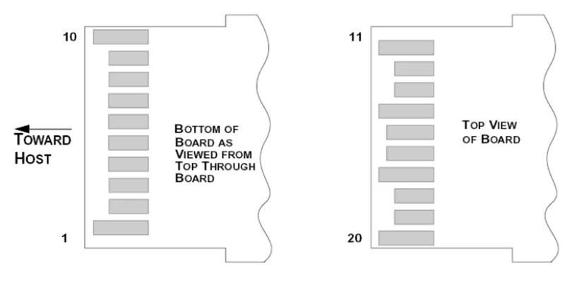
| Pins | Name |
Discription |
NOTE |
|
1 |
VeeT |
Transmitter Ground |
|
|
2 |
Tx Fault |
Transmitter Fault Indication |
1 |
|
3 |
Tx Disable |
Transmitter Disable |
2 |
|
4 |
MOD DEF2 |
Module Definition 2 |
3 |
|
5 |
MOD DEF1 |
Module Definition 1 |
3 |
|
6 |
MOD DEF0 |
Module Definition 0 |
3 |
|
7 |
RS0 |
Not Connected |
|
|
8 |
LOS |
Loss of Signal |
4 |
|
9 |
RS1 |
Not Connected |
|
|
10 |
VeeR |
Receiver Ground |
|
|
11 |
VeeR |
Receiver Ground |
|
|
12 |
RD- |
Inv. Received Data Output |
5 |
|
13 |
RD+ |
IReceived Data Output |
5 |
|
14 |
VeeR |
Receiver Ground |
|
|
15 |
VccR |
Receiver Power |
|
|
16 |
VccT |
Transmitter Power |
|
|
17 |
VeeT |
Transmitter Ground |
|
|
18 |
TD+ |
Transmit Data Input |
6 |
|
19 |
TD- |
Inv. Transmit Data Input |
6 |
|
20 |
VeeT |
Transmitter Ground |
Notes:
1. TX Fault is an open collector output, which should be pulled up with a 4.7k~10kΩ resistor on the host board to a voltage between 2.0V and Vcc+0.3V.
Logic 0 indicates normal operation; logic 1 indicates a laser fault of some kind. In the low state, the output will be pulled to less than 0.8V.
2. TX Disable is an input that is used to shut down the transmitter optical output. It is pulled up within the module with a 4.7k~10kΩ resistor. Its states are:
Low (0~0.8V): Transmitter on
(>0.8V, <2.0V): Undefined
High (2.0~3.465V): Transmitter Disabled
Open: Transmitter Disabled
3. MOD-DEF 0,1,2 are the module definition pins. They should be pulled up with a 4.7k~10kΩ resistor onthe host board. The pull-up voltage shall be VccT or VccR.
MOD-DEF 0 is grounded by the module to indicate that the module is present
MOD-DEF 1 is the clock line of two wire serial interface for serial ID
MOD-DEF 2 is the data line of two wire serial interface for serial ID
4. LOS is an open collector output, which should be pulled up with a 4.7k~10kΩ resistor on the host board to a voltage between 2.0V and Vcc+0.3V. Logic 0 indicates
normal operation; logic 1 indicates loss of signal. In the low state, the output will be pulled to less than 0.8V.
5. These are the differential receiver output. They are internally AC-coupled 100Ω differential lines which should be terminated with 100Ω (differential) at the user SERDES.
6. These are the differential transmitter inputs. They are AC-coupled, differential lines with 100Ω differential termination inside the module.
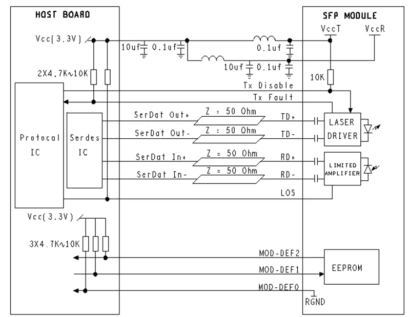
Recommended Application Circuit:
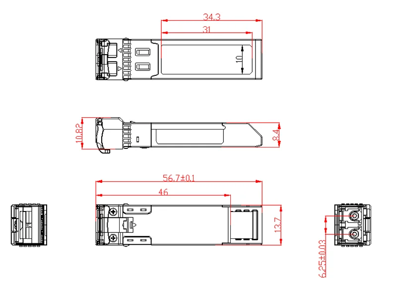
Outline drawing (mm):
Product detail pictures:
Related Product Guide:
Industrial Ethernet network and cable tester is ‘the first’ | Sfp Gpon Onu
Divergent customer plans, technology options affect 200G/400G transceiver deployment timing: LightCounting | Sfp Gpon Onu
"Control the quality by the details, show the power by quality". Our enterprise has strived to establish a remarkably efficient and stable team team and explored an effective excellent control system for Sfp 10 - 10G 1550nm 40KM LC connector dual fiber optic SFP+ module – HDV , The product will supply to all over the world, such as: Curacao, Palestine, Mecca, Ought to any of these products be of curiosity to you, remember to allow us to know. We are going to be satisfied to give you a quotation on receipt of one's in depth specs. We've our private experienced R&D enginners to meet any of one's requriements, We appear forward to receiving your enquires soon'and hope to have the opportunity to work together with you in the future. Welcome to check out our company.
This company has the idea of "better quality, lower processing costs, prices are more reasonable", so they have competitive product quality and price, that's the main reason we chose to cooperate.
Products categories

Write your message here and send it to us