


As a protective device, TVS tubes can effectively prevent electrostatic breakdown and protect circuits. When selecting TVS tubes, attention must be paid to their relevant parameters, otherwise unexpected problems may occur. VRWM, VBR, Vc, Ipp, Cd are important parameters for ESD/TVS device selection
Explanation:
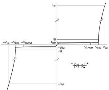
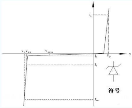
VBR: The point where the collapse voltage @ IT - TVS instantly becomes low impedance
VRWM: Maintain voltage - TVS is in a non-conductive state at this stage
VC: Clamping voltage @ Ipp - Clamping voltage is approximately 1.3 * VBR
VF: Forward conduction voltage @ IF - Forward voltage drop
ID: Reverse Leakage Current @ VRWM
IT: Test current for collapse voltage
IPP: Burst peak current
IF: Forward conduction current
When the pulse peak current IPP with a duration of 20mS flows through TVS, the pulse voltage is clamped by the ESD protection device, and the maximum peak voltage that occurs at both ends is VC. VC and IPP reflect the surge suppression capability of TVS. (Note: VC is the voltage provided by the diode in the cut-off state, that is, the voltage through TVS during ESD impulse state. It cannot be greater than the allowable limit voltage of the protected circuit, otherwise the device faces the risk of damage.).
Maximum Reverse Leakage Current @ VRWM
VRWM indicates that under the specified ID, the voltage value at both ends of the TVS device becomes the maximum reverse operating voltage. Usually VRWM=(0.8~0.9) VBR. At this voltage, the power consumption of the device is very small. (Note: When selecting the type, Vrwm should not be lower than the normal working voltage of the protected device or circuit. Generally, Vop<Vrwm<85% * Vc is used to connect TVS to the circuit without affecting normal circuit operation. Some chip manuals provided by manufacturers may not specifically reflect VC parameters, but VRWM is used to reflect the same. Even if VRWM meets the above conditions, the key still depends on the voltage value of clamp voltage VC. If VC does not meet the requirements, the protection circuit is still The power supply voltage of ONU equipment is usually 12V, and the TVS tube is generally selected to control VC between 14V and 16V.
The voltage at which the TVS transistor passes the specified test current It, which is the marked voltage indicating the conduction of the TVS transistor, i.e., from this point on, the device enters avalanche breakdown. VBR is the minimum breakdown voltage for TVS, and at 25 ℃, TVS will not experience avalanches below this voltage. When TVS flows through a specified 1mA current (IR), the voltage applied to the two poles of TVS is its minimum breakdown voltage VBR. In order to meet the international standard of IEC61000-4-2, TVS diodes must be able to handle a minimum of 8kV (contact) and 15kV (air) ESD impacts. Some semiconductor manufacturers have used higher impact resistance standards on their products. For certain portable device applications with special requirements, designers can select devices according to their needs.
The above is a brief overview of the Important Parameters of TVS Selection, which can be used as a reference. Our company has a strong technical team and can provide professional technical services to customers. At present, our company has diversified products: intelligent onu, communication optical module, optical fiber module, sfp optical module, olt equipment, Ethernet switch and other network equipment. If you need, you can understand them in depth.