


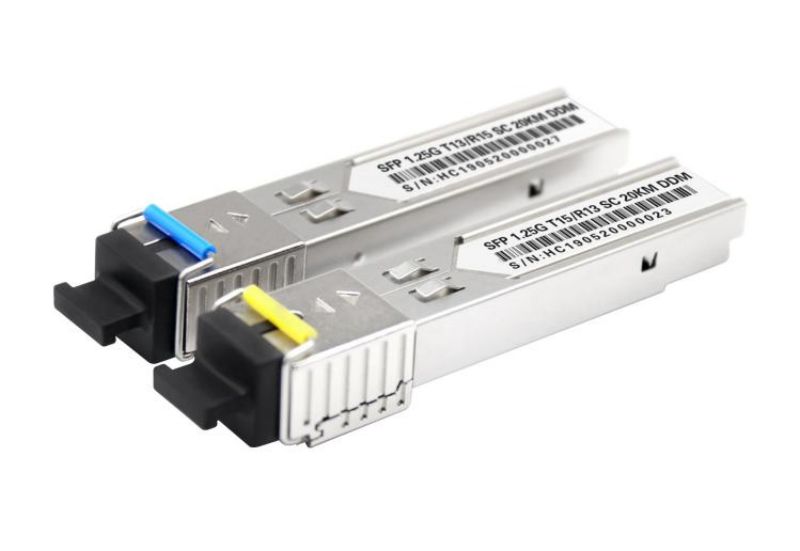
SFP (Small Form-factor Pluggable) is an upgraded version of GBIC (Gigabit Interface Converter), which is an interface device for converting gigabit electrical signals into optical signals. The design can be used for hot plug, and the SFP interface is widely used in switches. Ordinary routing products can be expanded to access function by supporting SFP interface.
Commissioning range: During the test phase:
Temperature: Industrial grade modules requia test temperature range: -40℃ ~ + 85℃; Scope of commercial grade modules testing requirements: -20℃ ~ + 70℃;
Optical power range: minimum: -23 dbm.
Test purpose:The bit error rate test is essentially to output a known data bit flow to the device under test, and then capture and analyze the data flow returned by the device under test. In order to achieve the same test results for different instruments, a special pseudo-random sequence is often applied, which is a standard derived from the definition of the communications industry. In simple terms: test for errors in data transfer. It is oneof the embodiments of the quality of the transmission signal.
Test requires equipment: Bit error tester, test board, optical module, computer, fiber cable, SMA copper axis, etc
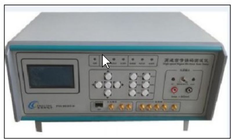
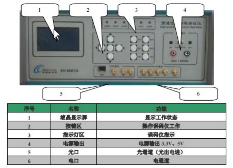
As shown in the figure, the error ERpanel is introduced
Test board: SMA coaxis are converted to optical signal
Optical module: as shown in the first figure of this article.
Optical fiber line: LC/SC single mode, multimode, according to the corresponding optical module
SMA copper axis: The only requirement: the frequency at which transmission can be achieved
test pattern:
1. Electric to optical: The electrical signal emitted by the error device is converted into optical signal through the test board and the optical module, and then input into the error meter.
2. Optical toelectric: The optical signal emitted by the error meter is converted into electrical signal through the test board and optical module, and then input into the error meter.
3.Electric to electric, using two optical modules.The electrical signal emitted from channel 1 is converted into optical signal through the test board and optical module 1. Then this optical signal is input into optical module 2, which is converted into electrical signal through the test board and optical module 2, and input back to the error meter for comparison.
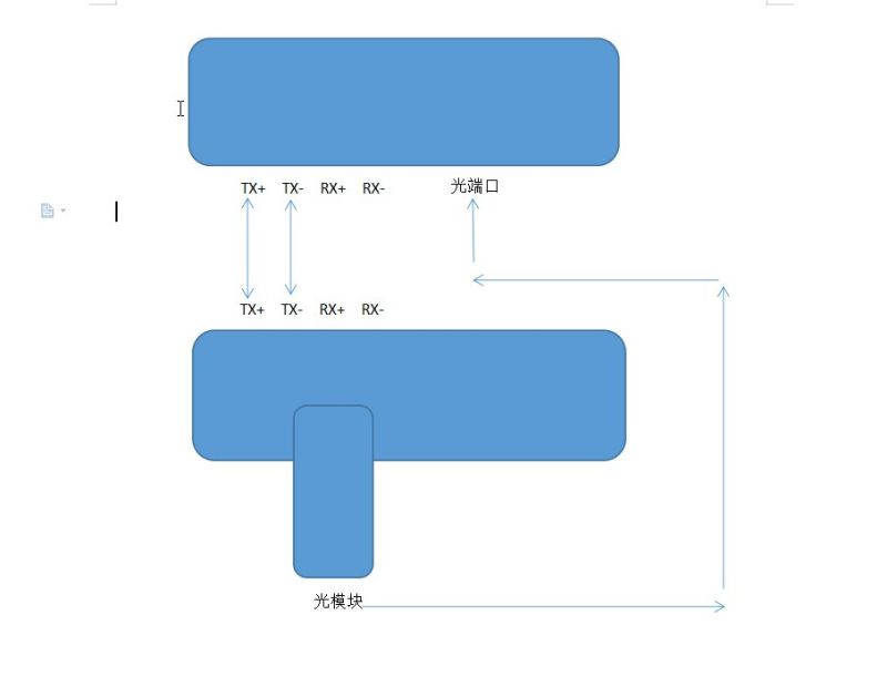
A simple electrolight mode as shown in Fig