


In the optical communication industry, optical modules are the most exposed. They have different physical sizes, and the number of channels and transmission rates vary greatly. How these modules are produced, what are their characteristics, and all the secrets are in the standard.
Older packaging standards such as GBIC, XPAK, X2, and Xenpak will be ignored, and the main energy will be focused on the more vigorous or newer standards, which will be evaluated one by one below.
SFF Standardization Organization: The SFF (small form-factor small package) standardization organization was established in August 1990. It initially developed 2.5-inch disk drives and expanded to other fields in November 1992. So far, SFF has become the most common and successful module standard in the field of optical module packaging. The optical module standards formulated by SFF mainly include SFP / QSFP / XFP.
SFP standard
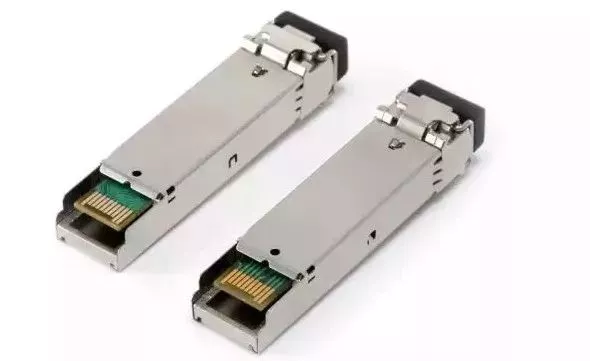
SFP (small form-factor Pluggable), a family of small form-factor pluggable transceivers, mainly used for Ethernet, fibre channel, Wireless CPRI, SONET: defines a single-channel SFP package from 1Gb / s to 28Gb / s that should be complied with Standard, its structure is shown in the figure below. First there was a declarative document, such as SFF-8402 proposed SFP28, SFF-8083 proposed SFP10 (the number at the end represents the transmission rate level, SFP10 is often written as SFP + now), this declaration document mentioned which technical requirements it cited These cited technical requirements collectively constitute the substantive standard for this module.
The SFP series technical specifications mainly include:
SFF-8432, defines the size of the module (mainly the size of the installation), the plugging force, and the specification of the module cage.
SFF-8071 defines the card slot connector on the HOST motherboard and the gold finger access sequence of the module motherboard.
SFF-8433, defines multiple side-by-side module cages and EMI shrapnel technical specifications.
SFF-8472, defines module memory and diagnostic management specifications.
SFF-8431 defines the power supply, low-speed electrical signals (communication lines), high-speed signals, timing, and memory read and write specifications.
Because the SFP support rate is getting higher and higher, the high-speed signal specification in SFF8431 does not apply to SFP16 / 28, so SFF-8431 was later split into SFF-8418 and SFF-8419. SFF-8418 specifically defines 10Gb / s high-speed electrical signal interface requirements. For physical interface requirements above 10Gb / s, refer to Fibre Channel. SFF-8419 specifically defines content other than high-speed signals in SFF-8431, which is suitable for all SFP series modules.
Therefore, SFP module structure design engineers must be familiar with SFP-8431. If you are a person who designs PCBs, writes software, or conducts testing, SFF-8472, SFF-8418, and SFF-8419 must be familiar with it.
QSFP standard
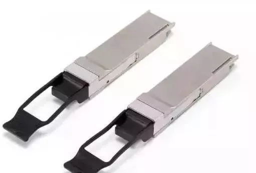
QSFP (Quad Small Form-factor Pluggable), a four-channel miniaturized pluggable transceiver, mainly used in Infiniband, Ethernet, Fibre Channel, OTN, SONET protocol family: QSFP upgrades a single-channel SFP to four channels with a volume of only It is more than doubled. For the same size switch, the QSFP switching capacity is 2.67 times that of SFP. The QSFP protocol was originally defined by INF-8438i, then upgraded to SFF-8436,
and then SFF-8436 was split into several parts for definition and reference. The architecture is now similar to SFP:
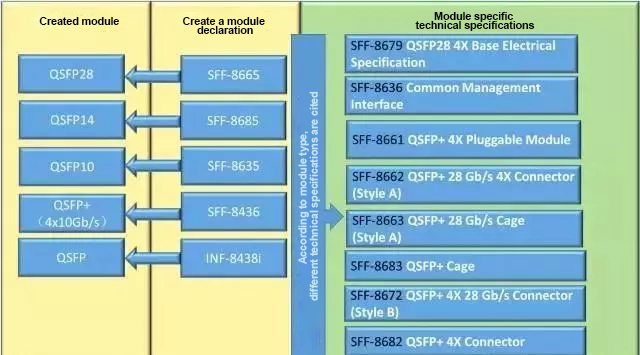
QSFP technical specifications mainly include:
SFF-8679, defines the high-speed signal, low-speed signal, power supply, timing specifications of the module, and defines the optical interface and pull ring color specifications.
SFF-8636, defines memory information, memory read and write operations.
SFF-8661, defines the size of the module, the size of the gold finger and the specification of the module’s insertion and removal force.
SFF-8662 and SFF-8663 define the cage and connector (type A) of the QSFP28 module.
SFF-8672 and SFF-8683 define the cages and connectors (type B) of the QSFP28 module.
SFF-8682 and SFF-8683 define the cages and connectors of QSFP14 and below rate modules.
Other supplementary information for QSFP can be viewed in the Infiniband protocol. (InfiniBand TM ArchitectureSpecification Volume )
XFP standard
XFP (10 Gb / s Small Form Factor Pluggable module, where X stands for 10 in Roman numerals and is mainly used for SONET OC-192, 10 Gigabit Ethernet, and fiber channel) protocol family: XFP It is a wavelength tunable module, which was originally defined by the XFP MSA and later submitted to the SFF organization for publication. The XFP protocol includes SFF-8477 and INF-8077.
The INF8077 protocol defines the size, electrical interface, memory information, communication control and diagnostics of the XFP module (the protocol includes all aspects of the module). SFF-8477 is mainly optimized for wavelength adjustment control.
CXP Standard
CXP (12x Small Form-factor Pluggable, 12-channel small pluggable package, where C stands for 100G, mainly used for Infiniband, fibre channel, Ethernet) protocol is mainly regulated by the Infiniband organization.
Annex A6 120 Gb / s 12x Small Form-factor pluggable (CXP) InterfaceSpecification for Cables, Active Cables & Transceivers provides all aspects of CXP specifications (can be downloaded free of charge at www.infinibandta.org). In addition, the SFF organization regulates shield cages and card slots for CXPs of different speed grades.
SFF-8617 Mini Multilane 12X Shielded Cage / Connector 12 channel CXP cage and module board slot specification.
SFF-8642 EIA-965 Mini Multilane 10 Gb / s 12X Shielded Cage / Connector (CXP10) 12x10Gb / s CXP module cage and module board slot specifications.
SFF-8647 Mini Multilane 14 Gb / s 12X Shielded Cage / Connector (CXP14) 12x14Gb / s CXP module cage and module board slot specifications.
SFF-8648 Mini Multilane 28 Gb / s 12X Shielded Cage / Connector (CXP28) 12x28Gb / s CXP module cage and module board slot specifications.
microQSFP (miniaturized QSFP), a multi-dimensional protocol established in 2015, is 4 channels like QSFP, but the size is only the size of an SFP module, and it supports 25G and 50G (PAM4 modulation) channel rates. Through the design of heat dissipation fins on the module housing, it has better thermal performance. “Micro QUAD SMALL FORM-FACTOR PLUGGABLE FOUR CHANNEL PLUGGABLE TRANSCEIVER, HOST CONNECTOR, & CAGE ASSEMBLY FORM FACTOR” details the micro-QSFP specification.
CFP package
Except for SFP and QSFP packages, CFP should be the most common form of packaging in optical modules. The C in the CFP represents 100 in the Roman numeral clock, so the CFP is mainly aimed at applications with a rate of 100G (including 40G) and above.
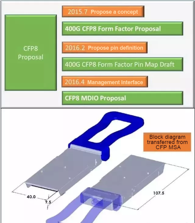
The CFP family mainly includes CFP / CFP2 / CFP4 / CFP8, of which CFP8 is still in the proposal stage.
Unlike the additional numbers 10 and 28 behind the QSFP, which represent the speed grade, the numbers behind the CFP represent a new generation, with a more compact size (except for CFP8) and a higher density.
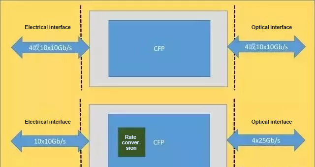
When the CFP package was first proposed, it was technically difficult to achieve a single 25Gb / s rate, so the electrical interface rate of each CFP was defined as a 10Gb / s level, and 40G and 40G were achieved through 4x10Gb / s and 10x10Gb / s electrical interfaces. 100G module speed. The size of the CFP module is so large that it can put a lot of functions on the motherboard into the module to complete [ASIC (SerDes)]. When the speed of each optical path does not match the circuit speed, you can complete the rate conversion through these circuits (Gear box) For example, the optical port 4X25Gb / s is converted into an electrical port 10x10Gb / s.
The size of CFP2 is only half that of CFP. The electrical interface can support a single 10Gb / s, or a single 25Gb / s or even 50Gb / s. Through the 10x10G, 4x25G, 8x25G, and 8x50G electrical interfaces, 100G / 200G / 400G module rates can be achieved.
The size of CFP4 is reduced to half that of CFP2. The electrical interface supports single 10Gb / s and 25Gb / s, and the module speed of 40G / 100G is achieved through 4x10Gb / s and 4x25Gb / s. CFP4 and QSFP modules are very similar, both are four-way, and both support 40G and 100G; the difference is that CFP4 modules have more powerful management functions and larger sizes (this is a disadvantage for high-density data communications), and can support larger functions. Power consumption, for speed grades above 25Gb / s and long-distance transmission scenarios (requires TEC temperature control, large power consumption), the advantages of CFP4 modules in power consumption and heat dissipation can be reflected.
Therefore, short-distance data communication is basically the world of QSFP; for 100G-LR4 10km applications, CFP4 and QSFP28 are equally divided.
The CFP family standards are shown in the following figure: each standard has 3 files, of which “CFPx MSA Hardware Specification Revision” is a programmatic file, which briefly describes the module concept, module management, electrical interface, mechanical size, optical interface, cheat Slots and other specifications, the other two documents define detailed mechanical dimensions.
CFP MSA also has two public technical specifications, PIN Allocation REV.25 specifies the module pin definition, and “CFP MSA Management Interface Specification” defines the module management control and register information in detail.
The high-speed electrical interface of the CFP module depends on the application, and references the CAUI, XLAUI, and CEI-28G / 56G electrical interface specifications in the IEEE802.3.
CFP8 is a package specifically proposed for 400G, and its size is equivalent to CFP2. The electrical interface supports channel speeds of 25Gb / s and 50Gb / s, and achieves 400G module speeds through 16x25G or 8×50 electrical interfaces. CFP8 is only a Proposal, there is no official standard for public download.
The CDFP MSA was established in 2013, and the CDFP packaging standard they released was the first 400G optical module packaging standard. At that time, the standard of the electrical interface was only 25Gb / s (OIF-CEI-28G-VSR), so the CDFP simply made 16 channels, and completed the 400G module rate through 16x25G, and it was specifically targeted for short-range applications below 2km.
If the 16-way electrical ports are arranged in a row, the volume will be extremely huge, so the CDFP module simply got two PCB boards together and used the MPO16 interface on the optical port. The entire module looks particularly fat! According to the arrangement of optical and electrical ports, there are three module sizes in total.
The latest CDFP standard is: “400 Gb / s (16 X 25 GB / s) PLUGGABLE TRANSCEIVER Rev 3.0″ which specifies the electrical interface, management interface, optical interface, module / slot / cage size of the CDFP module, EMI / ESD related content. Today, PAM4 is so hot, it is estimated that this package is very tested.
The latest packaging standard that supports 400G should be QSFP-DD. This organization was established in February 2016 and released the latest standard “QSFP DOUBLE DENSITY 8X PLUGGABLE TRANSCEIVER Rev 1.0″ in September 2016. QSFP-DD is roughly the same size as QSFP (just because there is an extra row of circuits, a little bit longer). The core change is to double the QSFP electrical interface from four to eight and support 50Gb / s channel rate 8X50 is 400G). The QSFP-DD electrical interface is compatible with QSFP, but not vice versa.
The above discussions are all 100G and 400G optical modules. Let’s look at the approachable CSFP. Although the latest CSFP standard is the “campact SFP specifications” released in 2009, it is not outdated at all. Campact means more compact than SFP optical modules, and the number of channels can also be flexibly configured. CSFP defines 3 types: 1CH campact SFP, 2CH campact SFP option1, and 2CH campact SFP option2.
Packaging black technology CFP2—ACO
Finally, let’s take a look at the most advanced black technology in optical module packaging standards: CFP2-ACO. It is mainly defined by OIF and references the mechanical dimensions of CFP2. The back ACO means analog coherent optical module. It mainly consists of a narrow line-width tunable laser, a modulator, and a coherent receiver. The DSP (digital signal processing) is placed outside the module. This module is incredible. With DP-QPSK and DP-xQAM modulation technology, the single-wavelength rate can easily exceed 100Gb / s, and the transmission distance can exceed 2000km.