In the EPON system, the OLT is connected to multiple ONUs (optical network units) through a POS (passive optical splitter). As the core of EPON, OLT optical modules will directly affect the operation of the entire 10G EPON system.
1.Introduction to 10G EPON symmetrical OLT optical module
The 10G EPON symmetrical OLT optical module uses the uplink burst reception and downlink continuous transmission modes, which are mainly used for optical / electrical conversion in 10G EPON systems.
The receiving part consists of a TIA (transimpedance amplifier), an APD (Avalanche Photodiode) at 1270 / 1310nm, and two LA (limiting amplifiers) at 1.25 and 10.3125 Gbit / s rates.
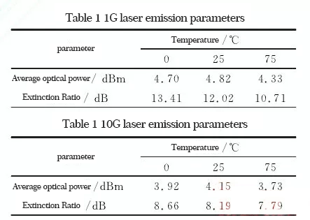
The transmitting end is composed of a 10G EML (electro-absorption modulation laser) and a 1.25 Gbit / s DFB (distributed feedback laser), and its emission wavelengths are 1577 and 1490nm, respectively.
The driving circuit includes a digital APC (Automatic Optical Power Control) circuit and a TEC (Temperature Compensation) circuit for maintaining a stable 10G laser emission wavelength. The transmitting and receiving parameter monitoring is implemented by the single chip microcomputer according to the SFF-8077iv4.5 protocol.
Because the receiving end of the OLT optical module uses burst reception, the reception setup time is particularly important. If the reception settling time is long, it will greatly affect the sensitivity, and may even cause the burst reception to not work properly. According to the requirements of the IEEE 802.3av protocol, the establishment time of a 1.25Gbit / s burst reception must be <400 ns, and the burst reception sensitivity must be <-29.78 dBm with a bit error rate of 10-12; and 10.3125 Gbit / s The burst reception setup time must be <800ns, and the burst reception sensitivity must be <-28.0 dBm with a bit error rate of 10-3.
2.10G EPON symmetrical OLT optical module design
2.1 Design scheme
The 10G EPON symmetrical OLT optical module is composed of a triplexer (single-fiber three-way module), transmitting, receiving, and monitoring. The triplexer includes two lasers and a detector. The transmitted light and the received light are integrated into the optical device through WDM (Wavelength Division Multiplexer) to achieve single-fiber bidirectional transmission. Its structure is shown in Figure 1.
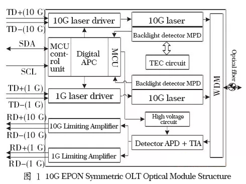
The transmitting part consists of two lasers, whose main function is to convert 1G and 10G electrical signals into optical signals, respectively, and to maintain the optical power stability in a closed loop state through a digital APC circuit. At the same time, the single-chip microcomputer controls the magnitude of the modulation current to obtain the extinction ratio required by the system. The TEC circuit is added to the 10G transmitting circuit, which greatly stabilizes the output wavelength of the 10G laser. The receiving part uses APD to convert the detected burst optical signal into an electrical signal, and outputs it after amplification and shaping. In order to ensure that the sensitivity can reach the ideal range, it is necessary to provide a stable high pressure to the APD at different temperatures. The one-chip computer achieves this goal by controlling the APD high-voltage circuit.
2.2 Implementation of dual-rate burst reception
The receiving part of the 10G EPON symmetric OLT optical module uses a burst receiving method. It needs to receive burst signals of two different rates of 1.25 and 10.3125 Gbit / s, which requires the receiving part to be able to distinguish the optical signals of these two different rates well in order to obtain stable output electrical signals. Two schemes for implementing dual-rate burst reception of OLT optical modules are proposed here.
Because the input optical signal uses TDMA (Time Division Multiple Access) technology, only one rate of burst light may exist at the same time. The input signal can be separated in the optical domain through a 1: 2 optical splitter, such as Shown in Figure 2. Or use only a high-speed detector to convert 1G and 10G optical signals into weak electrical signals, and then separate two electrical signals with different rates through a larger bandwidth TIA, as shown in Figure 3.
The first scheme shown in Figure 2 will bring a certain insertion loss when the light passes through the 1: 2 optical splitter, which must amplify the input optical signal, so an optical amplifier is installed in front of the optical splitter. The separated optical signals are then subjected to optical / electrical conversion by detectors of different rates, and finally two kinds of stable electrical signal outputs are obtained. The biggest disadvantage of this solution is that an optical amplifier and a 1: 2 optical splitter are used, and two detectors are needed to convert the optical signal, which increases the complexity of the implementation and increases the cost.
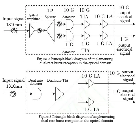
In the second scheme shown in FIG. 3, the input optical signal only needs to pass through a detector and a TIA to achieve separation in the electric domain. The core of this solution lies in the selection of TIA, which requires TIA to have a bandwidth of 1 ~ 10Gbit / s, and at the same time TIA has fast response within this bandwidth. Only through the current parameter of TIA can get the response value quickly, the receiving sensitivity can be well guaranteed. This solution greatly reduces the complexity of implementation and keeps costs under control. In the actual design, we generally choose the second scheme to achieve dual-rate burst reception.
2.3 Design of the hardware circuit at the receiving end
Fig. 4 is the hardware circuit of the burst receiving part. When there is a burst optical input, the APD converts the optical signal into a weak electrical signal and sends it to the TIA. The signal is amplified by the TIA into a 10G or 1G electrical signal. The 10G electrical signal is input to the 10G LA through the positive coupling of the TIA, and the 1G electrical signal is input to the 1G LA through the negative coupling of the TIA. Capacitors C2 and C3 are coupling capacitors used to achieve 10G and 1G AC-coupled output. The AC-coupled method was chosen because it is simpler than the DC-coupled method.
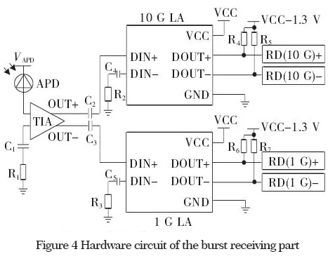
However, the AC coupling has the charge and discharge of the capacitor, and the response speed to the signal is affected by the charge and discharge time constant, that is, the signal cannot be responded to in time. This feature is bound to lose a certain amount of reception settling time, so it is important to choose how large the AC coupling capacitor. If a smaller coupling capacitor is selected, the settling time can be shortened, and the signal transmitted by the ONU in each time slot can be completely received without affecting the reception effect because the reception settling time is too long and the arrival of the next time slot.
However, too small capacitance will affect the coupling effect and greatly reduce the stability of reception. Larger capacitance can reduce system jitter and improve the sensitivity of the receiving end. Therefore, in order to take into account the reception settling time and reception sensitivity, the appropriate coupling capacitors C2 and C3 need to be selected. In addition, in order to ensure the stability of the input electrical signal, a coupling capacitor and a matching resistor with a resistance of 50Ω are connected to the negative terminal of LA.
LVPECL (Low Voltage Positive Emitter Coupling Logic) circuit composed of resistors R4 and R5 (R6 and R7) and a 2.0 V DC voltage source through the differential signal output by 10G (1G) LA. electric signal.
2.4 Launch section
The transmitting part of the 10G EPON symmetric OLT optical module is mainly divided into two parts of 1.25 and 10G transmitting, which respectively send signals with a wavelength of 1490 and 1577 nm to the downlink. Taking the 10G transmitting part as an example, a pair of 10G differential signals enters a CDR (Clock Shaping) chip, is AC-coupled to a 10G driver chip, and finally is differentially input into a 10G laser. Because the temperature change will have a great influence on the laser emission wavelength, in order to stabilize the wavelength to the level required by the protocol (the protocol requires 1575 ~ 1580nm), the working current of the TEC circuit needs to be adjusted, so that the output wavelength can be well controlled.
3. Test results and analysis
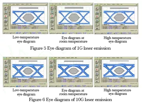
The main test indicators of the 10G EPON symmetric OLT optical module include the receiver setup time, receiver sensitivity, and transmit eye diagram. The specific tests are as follows:
(1) Receive setup time
Under the normal working environment of uplink burst optical power of -24.0 dBm, the optical signal emitted by the burst light source is used as the measurement starting point, and the module receives and establishes a complete electrical signal as the measurement end point, ignoring the time delay of light in the test fiber.The measured 1G burst reception setup time is 76.7 ns, which meets the international standard of <400 ns; the 10G burst reception setup time is 241.8 ns, which also meets the international standard of <800 ns.
3. Test results and analysis
The main test indicators of the 10G EPON symmetric OLT optical module include the receiver setup time, receiver sensitivity, and transmit eye diagram. The specific tests are as follows:
(1) Receive setup time
Under the normal working environment of uplink burst optical power of -24.0 dBm, the optical signal emitted by the burst light source is used as the measurement starting point, and the module receives and establishes a complete electrical signal as the measurement end point, ignoring the time delay of light in the test fiber. The measured 1G burst reception setup time is 76.7 ns, which meets the international standard of <400 ns; the 10G burst reception setup time is 241.8 ns, which also meets the international standard of <800 ns.