


Advantages of fiber optic communication:
● Large communication capacity
● Long relay distance
● No electromagnetic interference
● Rich resources
● Light weight and small size
A Brief History of Optical Communications
More than 2000 years ago, the beacon-lights, semaphores
1880, optical telephone-wireless optical communication
1970, fiber optic communications
● In 1966, “Father of Optical Fiber”, Dr. Gao Yong first proposed the idea of optical fiber communication.
● In 1970, Bell Yan Institute’s Lin Yanxiong was a semiconductor laser that could work continuously at room temperature.
● In 1970, Corning’s Kapron made a loss of 20dB / km fiber.
● In 1977, Chicago’s first commercial line of 45Mb / s.
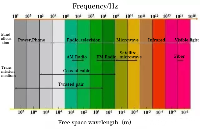
Electromagnetic spectrum
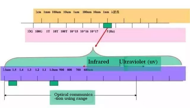
Communication band division and corresponding transmission media
Refraction / reflection and total reflection of light
Because light travels differently in different substances, when light is emitted from one substance to another, refraction and reflection occur at the interface between the two substances. Moreover, the angle of the refracted light varies with the angle of the incident light. When the angle of the incident light reaches or exceeds a certain angle, the refracted light will disappear, and all the incident light will be reflected back. This is the total reflection of the light. Different materials have different refraction angles for the same wavelength of light (that is, different materials have different refractive indices), and the same materials have different refraction angles for different wavelengths of light. Optical fiber communication is based on the above principles.
Reflectivity distribution: An important parameter to characterize optical materials is the refractive index, which is represented by N. The ratio of the speed of light C in the vacuum to the speed of light V in the material is the refractive index of the material.
N = C / V
The refractive index of quartz glass for optical fiber communication is about 1.5.
Fiber structure
Fiber bare fiber is generally divided into three layers:
The first layer: the center high refractive index glass core (core diameter is generally 9-10μm, (single mode) 50 or 62.5 (multimode).
The second layer: the middle is the low refractive index silica glass cladding (the diameter is generally 125μm).
The third layer: the outermost is a resin coating for reinforcement.
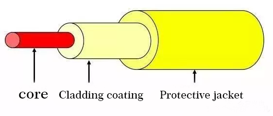
1) core: high refractive index, used to transmit light;
2) Cladding coating: low refractive index, forming a total reflection condition with the core;
3) Protective jacket: It has high strength and can withstand large impacts to protect the optical fiber.
3mm optical cable: orange, MM, multi-mode; yellow, SM, single-mode
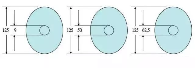
Fiber size
The outer diameter is generally 125um (average 100um per hair)
Inner diameter: single mode 9um; multimode 50 / 62.5um
Numerical aperture
Not all the light incident on the end face of the optical fiber can be transmitted by the optical fiber, but only incident light within a certain range of angles. This angle is called the numerical aperture of the fiber. A larger numerical aperture of the optical fiber is advantageous for the docking of the optical fiber. Different manufacturers have different numerical apertures.
Type of fiber
According to the transmission mode of light in the optical fiber, it can be divided into:
Multi-Mode (abbreviation: MM); Single-Mode (abbreviation: SM)
Multimode fiber: The center glass core is thicker (50 or 62.5μm) and can transmit light in multiple modes. However, its inter-mode dispersion is large, which limits the frequency of transmitting digital signals, and it will become more serious with increasing distance. For example: 600MB / KM fiber has only 300MB bandwidth at 2KM. Therefore, the transmission distance of multi-mode fiber is relatively short, generally only a few kilometers.
Single-mode fiber: The center glass core is relatively thin (core diameter is generally 9 or 10 μm), and can only transmit light in one mode. In fact, it is a kind of step-type optical fiber, but the core diameter is very small. In theory, only the direct light of a single propagation path is allowed to enter the fiber and propagate straight in the fiber core. The fiber pulse is barely stretched. Therefore, its inter-mode dispersion is small and suitable for remote communication, but its chromatic dispersion plays a major role. In this way, single-mode fiber has higher requirements for the spectral width and stability of the light source, that is, the spectral width is narrow and the stability is good. .
Classification of optical fibers
By material:
Glass fiber: The core and cladding are made of glass, with small loss, long transmission distance and high cost;
Rubber-covered silicon optical fiber: the core is glass and the cladding is plastic, which has similar characteristics to glass fiber and lower cost;
Plastic optical fiber: Both the core and the cladding are plastic, with large loss, short transmission distance, and low price. Mostly used for home appliances, audio, and short-distance image transmission.
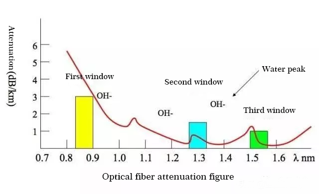
According to the optimal transmission frequency window: conventional single-mode fiber and dispersion-shifted single-mode fiber.
Conventional type: The optical fiber production house optimizes the optical fiber transmission frequency on a single wavelength of light, such as 1300nm.
Dispersion-shifted type: The fiber optics producer optimizes the fiber transmission frequency on two wavelengths of light, such as: 1300nm and 1550nm.
Abrupt change: The refractive index of the fiber core to the glass cladding is abrupt. It has low cost and high inter-mode dispersion. Suitable for short-distance low-speed communication, such as industrial control. However, single-mode fiber uses a mutation type because of the small inter-mode dispersion.
Gradient fiber: the refractive index of the fiber core to the glass cladding is gradually reduced, allowing high-mode light to propagate in a sinusoidal form, which can reduce dispersion between modes, increase fiber bandwidth, and increase transmission distance, but the cost is higher Mode fiber is mostly graded fiber.
Common fiber specifications
Fiber size:
1) Single mode core diameter: 9 / 125μm, 10 / 125μm
2) Outer cladding diameter (2D) = 125 μm
3) Outer coating diameter = 250 μm
4) Pigtail: 300μm
5) Multimode: 50 / 125μm, European standard; 62.5 / 125μm, American standard
6) Industrial, medical and low-speed networks: 100 / 140μm, 200 / 230μm
7) Plastic: 98 / 1000μm, used for automobile control
Fiber attenuation
The main factors that cause fiber attenuation are: intrinsic, bending, squeezing, impurities, unevenness and butt.
Intrinsic: It is the inherent loss of the optical fiber, including: Rayleigh scattering, intrinsic absorption, etc.
Bend: When the fiber is bent, the light in part of the fiber will be lost due to scattering, resulting in loss.
Squeezing: loss caused by slight bending of the fiber when it is squeezed.
Impurities: Impurities in an optical fiber absorb and scatter light transmitted in the fiber, causing losses.
Non-uniform: The loss caused by the uneven refractive index of the fiber material.
Docking: Loss generated during fiber docking, such as: different axes (single-mode fiber coaxiality requirement is less than 0.8 μm), the end face is not perpendicular to the axis, the end face is uneven, the butt core diameter does not match, and the splicing quality is poor.
Type of optical cable
1) According to the laying methods: self-supporting overhead optical cables, pipeline optical cables, armored buried optical cables and submarine optical cables.
2) According to the structure of the optical cable, there are: bundled tube optical cable, layer twisted optical cable, tight-hold optical cable, ribbon optical cable, non-metal optical cable and branchable optical cable.
3) According to the purpose: optical cables for long-distance communication, outdoor optical cables for short-distance, hybrid optical cables, and optical cables for buildings.
Connection and termination of optical cables
The connection and termination of optical cables are the basic skills that optical cable maintenance personnel must master.
Classification of optical fiber connection technology:
1) The connection technology of optical fiber and the connection technology of optical cable are two parts.
2) The end of the optical cable is similar to the connection of the optical cable, except that the operation should be different due to the different connector materials.
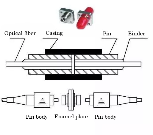
Type of fiber connection
Fiber optic cable connection can generally be divided into two categories:
1) Fixed connection of optical fiber (commonly known as dead connector). Generally use optical fiber fusion splicer; used for the direct head of optical cable.
2) The active connector of optical fiber (commonly known as the live connector). Use removable connectors (commonly known as loose joints). For fiber jumper, equipment connection, etc.
Due to the incompleteness of the end face of the optical fiber and the non-uniformity of the pressure on the end face of the optical fiber, the splice loss of the optical fiber by one discharge is still relatively large, and the secondary discharge fusion method is now used. First, preheat and discharge the end face of the fiber, shape the end face, remove dust and debris, and make the end pressure of the fiber uniform by preheating.
Monitoring method for optical fiber connection loss
There are three methods for monitoring fiber connection loss:
1. Monitor on the splicer.
2. Monitoring of light source and optical power meter.
3.OTDR measurement method
Operation method of optical fiber connection
Optical fiber connection operations are generally divided into:
1. Handling of fiber end faces.
2. Connection installation of optical fiber.
3. Splicing of optical fiber.
4. Protection of optical fiber connectors.
5. There are five steps for the remaining fiber tray.
Generally, the connection of the entire optical cable is performed according to the following steps:
Step1: a lot of good length, open and strip the optical cable, remove the cable sheath
Step 2: Clean and remove the petroleum filling paste in the optical cable.
Step 3: Bundle the fiber.
Step 4: Check the number of fiber cores, perform fiber pairing, and check whether the fiber color labels are correct.
Step 5: Strengthen heart connection;
Step 6: Various auxiliary line pairs, including business line pairs, control line pairs, shielded ground lines, etc. (if the above-mentioned line pairs are available.
Step 7: Connect the fiber.
Step 8: Protect the optical fiber connector;
Step 9: the inventory storage of the remaining fiber;
Step 10: Complete the connection of the optical cable jacket;
Step 11: Protection of fiber optic connectors
Fiber loss
1310 nm: 0.35 ~ 0.5 dB / Km
1550 nm: 0.2 ~ 0.3dB / Km
850 nm: 2.3 to 3.4 dB / Km
Optical fiber fusion point loss: 0.08dB / point
Fiber splicing point 1 point / 2km
Common fiber nouns
1) Attenuation
Attenuation: energy loss when light is transmitted in optical fiber, single-mode fiber 1310nm 0.4 ~ 0.6dB / km, 1550nm 0.2 ~ 0.3dB / km; plastic multimode fiber 300dB / km
2) Dispersion
Dispersion: The bandwidth of light pulses is increased after traveling a certain distance along the fiber. It is the main factor limiting the transmission rate.
Inter-mode dispersion: Occurs only in multimode fibers, because different modes of light travel along different paths.
Material dispersion: Different wavelengths of light travel at different speeds.
Waveguide dispersion: This occurs because light energy travels at slightly different speeds as it travels through the core and cladding. In single-mode fiber, it is very important to change the dispersion of the fiber by changing the internal structure of the fiber.
Fiber Type
G.652 zero dispersion point is around 1300nm
G.653 zero dispersion point is around 1550nm
G.654 negative dispersion fiber
G.655 dispersion-shifted fiber
Full wave fiber
3) scattering
Due to the imperfect basic structure of light, the loss of light energy is caused, and the transmission of light at this time no longer has good directivity.
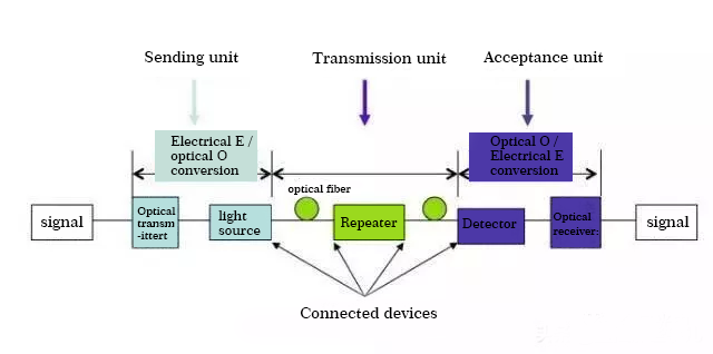
Basic knowledge of fiber optic system
Introduction to the architecture and functions of a basic fiber optic system:
1. Sending unit: converts electrical signals into optical signals;
2. Transmission unit: a medium carrying optical signals;
3. Receiving unit: receives optical signals and converts them into electrical signals;
4. Connect the device: connect the optical fiber to the light source, light detection and other optical fibers.
Common connector types
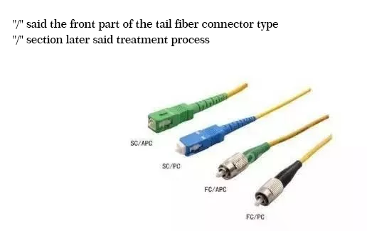
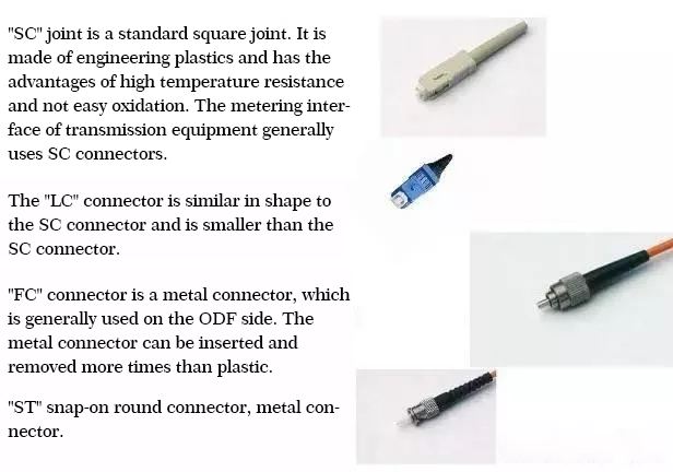
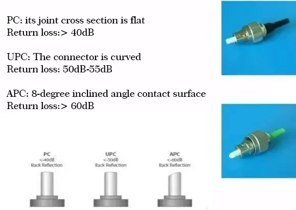
Connector end face type
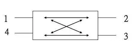
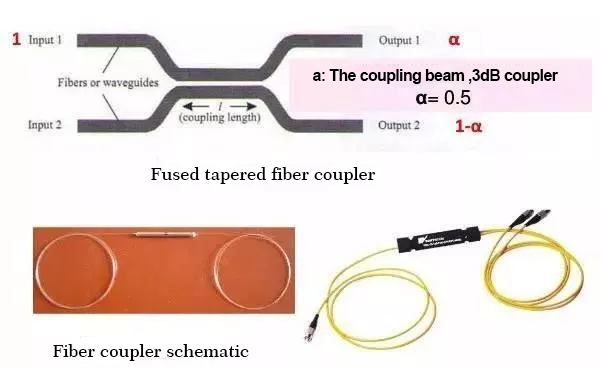
Coupler
The main function is to distribute optical signals. Important applications are in optical fiber networks, especially in local area networks and in wavelength division multiplexing devices.
basic structure
The coupler is a bidirectional passive device. The basic forms are tree and star. The coupler corresponds to the splitter.
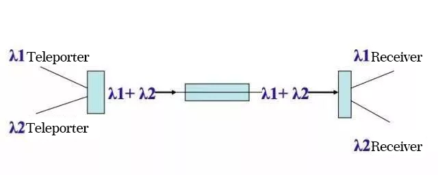
WDM
WDM—Wavelength Division Multiplexer transmits multiple optical signals in one optical fiber. These optical signals have different frequencies and different colors. The WDM multiplexer is to couple multiple optical signals into the same optical fiber; the demultiplexing multiplexer is to distinguish multiple optical signals from one optical fiber.
Wavelength Division Multiplexer (Legend)
Definition of pulses in digital systems:
1. Amplitude: The height of the pulse represents the optical power energy in the fiber optic system.
2. Rise time: the time required for the pulse to rise from 10% to 90% of the maximum amplitude.
3. Fall time: the time required for the pulse to fall from 90% to 10% of the amplitude.
4. Pulse width: The width of the pulse at the 50% amplitude position, expressed in time.
5. Cycle: pulse specific time is the working time required to complete a cycle.
6. Extinction ratio: The ratio of 1 signal light power to 0 signal light power.
Definition of common units in optical fiber communication:
1.dB = 10 log10 (Pout / Pin)
Pout: output power; Pin: input power
2. dBm = 10 log10 (P / 1mw), which is a widely used unit in communication engineering; it usually represents the optical power with 1 milliwatt as the reference;
example: –10dBm means that the optical power is equal to 100uw.
3.dBu = 10 log10 (P / 1uw)