


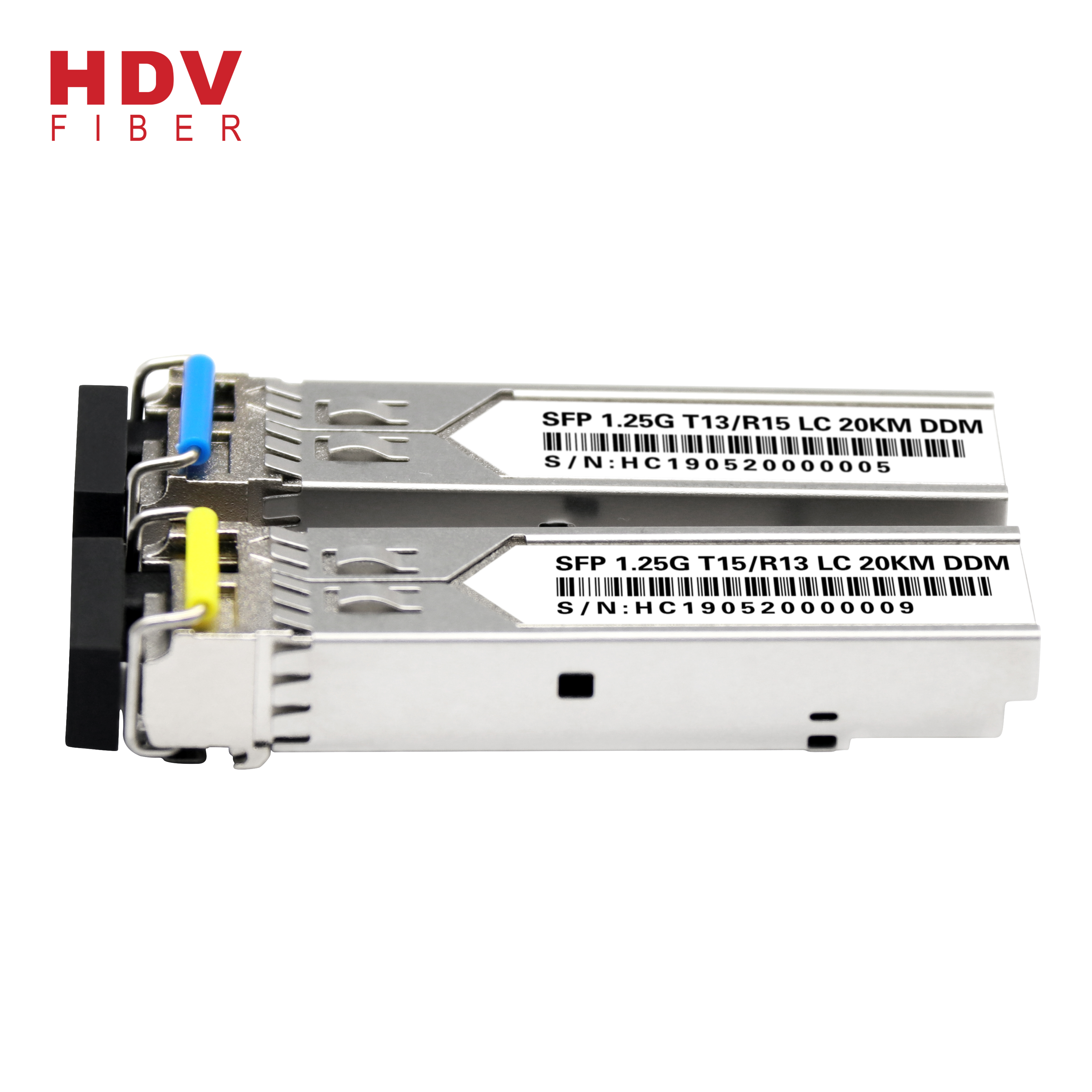

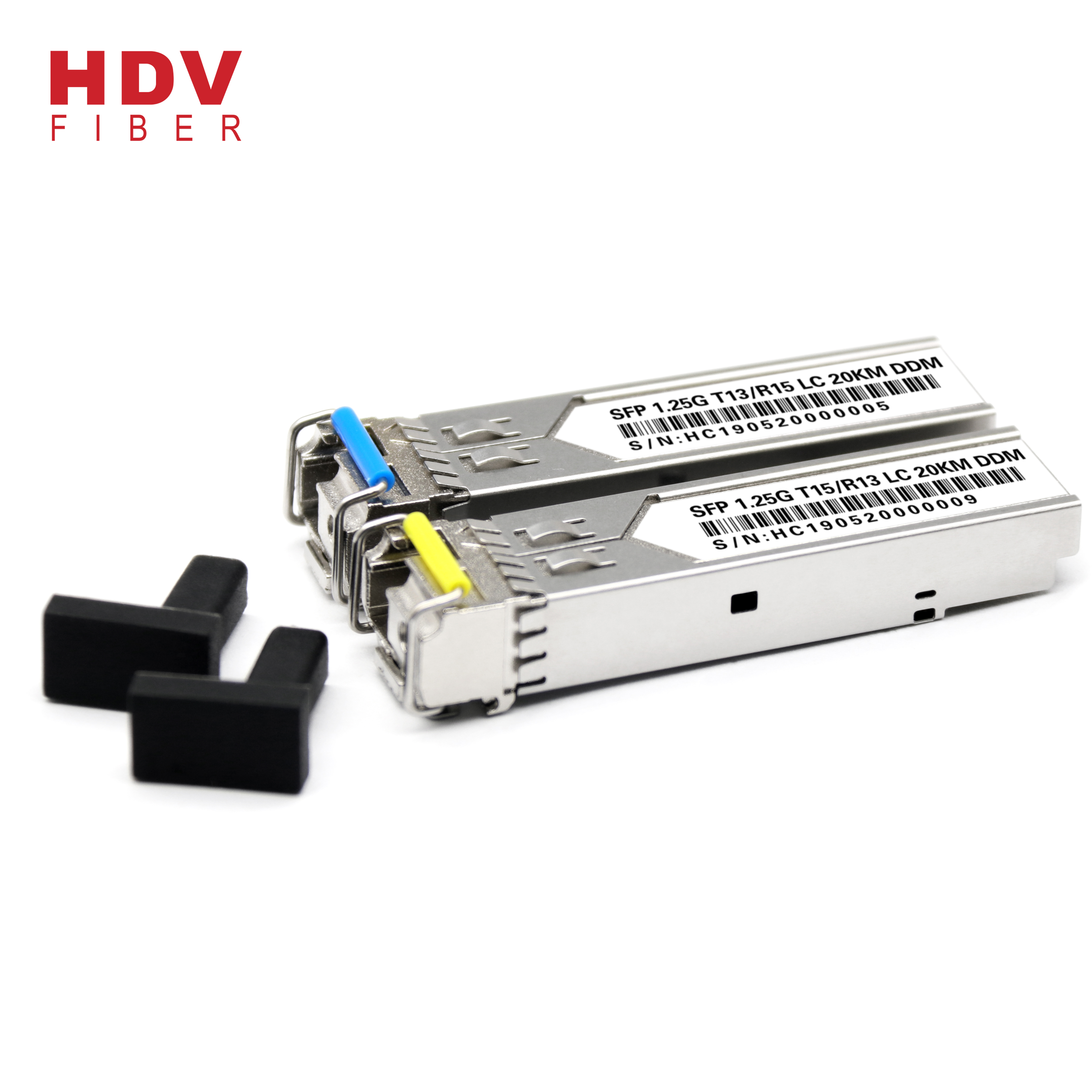
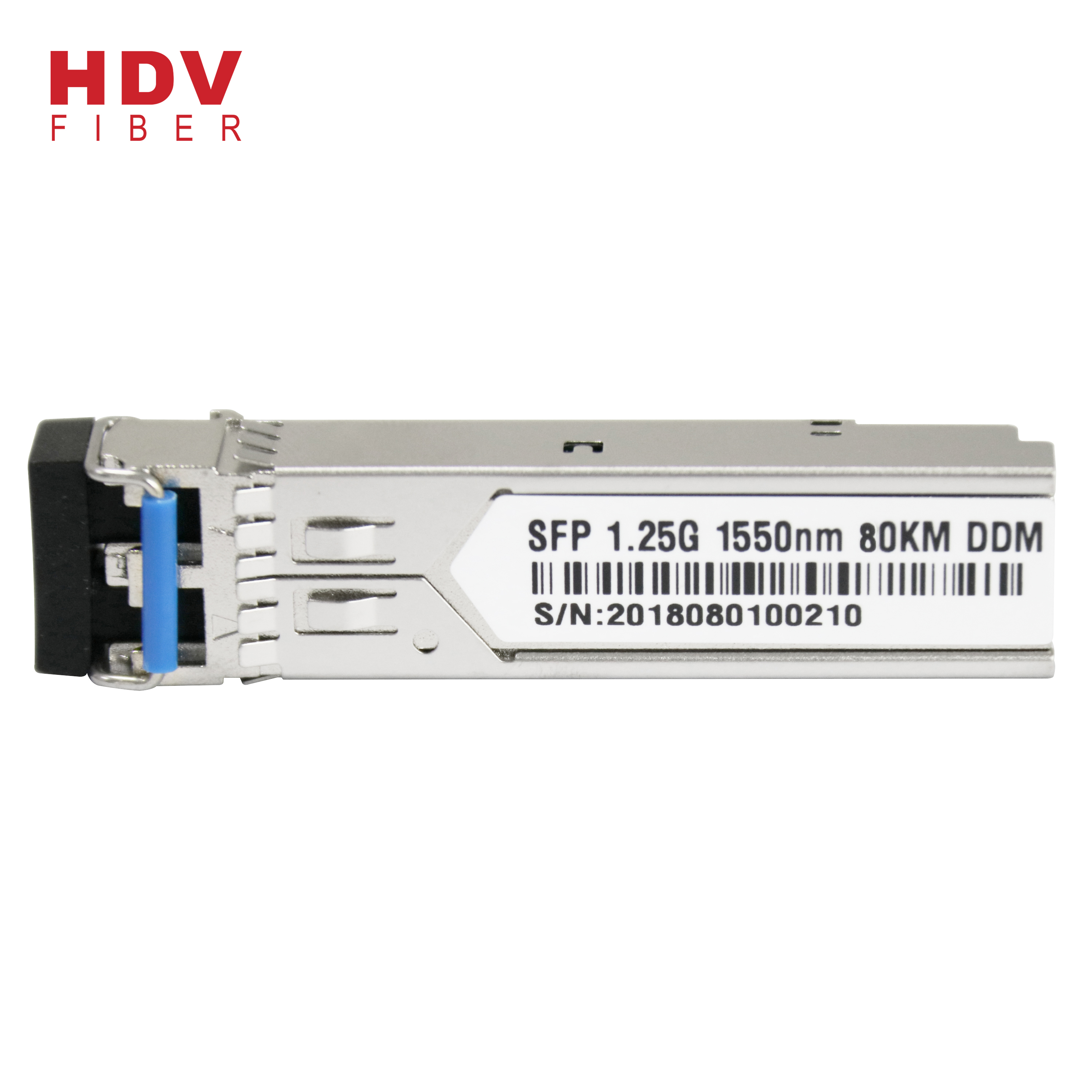
Good User Reputation for Sfp Module 1.25 - 20km Single Mode Lc Connector 1.25g Single Fiber Sfp Transceiver Optic Module – HDV Detail:
Applications:
- 1X fiber channel
- Video monitor system
- Telecommunication system
Product parameters:
|
Part No. |
Wavelength |
Connector |
Temp. |
TX Power (dBm) |
RX Sens (Max.) (dBm) |
Distance |
|
SFP3524-F11LC-20 |
T 1310FP/R 1550 |
LC |
-20 to 70 |
-9 to-3 |
-21 |
20km |
|
SFP5324-D11LC-20 |
T 1550DFB/R 1310 |
LC |
-20 to 70 |
-15 to-3 |
-21 |
|
|
SFP5324-D11LC-40 |
T 1550DFB/R 1310 |
LC |
-20 to 70 |
-9 to-3 |
-24 |
40km |
|
SFP3524-D11LC-40 |
T 1310DFB/R 1550 |
LC |
-20 to 70 |
-5to-0 |
-24 |
|
|
SFP5424-D11LC-80 |
T 1550DFB/R 1310 |
LC |
-20 to 70 |
-3 to2 |
-26 |
80km |
|
SFP4524-D11LC-80 |
T 1490DFB/R 1550 |
LC |
-20 to 70 |
-3 to2 |
-26 |
Ordering Information:
Example
SFP 35 24 -F 1 1 LC-20
SFP 35 24 -F 1 1 LC-20
|
Sign |
Mean |
Description |
|||||
|
SFP |
Module type |
SFP=Single fiber SFP transceiver |
|||||
|
35 |
Center wave |
35=1310tx/1550rx |
53=1550tx/1310rx |
45=1490tx/1550rx |
54=1550tx/1490rx |
||
|
24 |
Transmitter Rate |
03=155M |
03=622M |
24=1.25G |
48=2.5G |
60=3.125G |
|
|
F |
Laser type |
F=FP |
D=DFB |
C=CWDM |
V=VCSEL |
||
|
1 |
Operating T |
1=0~+70℃ |
2=-40~+85℃ |
||||
|
2 |
DDMI |
1=NO DDM |
2=DDMI |
||||
|
LC |
Connector |
SC=SC |
LC=LC |
||||
|
20 |
Distance |
022=220M |
055=550M |
5=5KM |
10=10KM |
||
|
20=20KM |
40=40KM |
80=80KM |
100=100KM |
||||
Absolute Maximum Ratings:
|
Parameter |
Symbol |
Min |
Max |
Unit |
|
|
Storage Temperature |
TS |
-40 |
+85 |
℃ |
|
|
Operating Temperature |
TOP |
Commercial level |
-20 |
+70 |
℃ |
|
industrial level |
-40 |
85 |
|||
|
Supply Voltage |
VCC |
-0.5 |
+4.5 |
V |
|
|
Voltage on Any Pin |
VIN |
0 |
VCC |
V |
|
|
Soldering Temperature ,Time |
- |
260℃, 10 S |
℃,S |
||
Recommended Operating Conditions:
|
Parameter |
Symbol |
Min. |
Typ |
Max. |
Unit |
|
|
Ambient Temperature |
TAMB |
Commercial level |
0 |
- |
70 |
℃ |
|
industrial level |
-40 |
85 |
||||
|
Power Supply Voltage |
V CC-VEE |
3 |
3.3 |
3.6 |
V |
|
Operating Conditions:
1. Transmitter(T=25℃, Vcc=3~3.6V (+3.3V))
|
Parameter |
Symbol |
Min. |
Typ |
Max. |
Unit |
|||||
|
Center Wavelength |
lc |
1520 |
1550 |
1580 |
nm |
|||||
|
1280 |
1310 |
1340 |
||||||||
|
1470 |
1490 |
1510 |
||||||||
|
Spectral width |
△l |
FP@RMS |
- |
2 |
4 |
nm |
||||
|
DFB@-20dB FWHM |
- |
- |
1 |
|||||||
|
Output Power |
0~20km |
1.25G |
1310 FP |
Po |
-9 |
- |
-3 |
dBm |
||
|
14/15 DFB |
-15 |
-3 |
||||||||
|
40km |
1.25G |
14/15 DFB |
-9 |
- |
-3 |
|||||
|
1310 DFB |
-5 |
-0 |
||||||||
|
60km |
1.25G |
14/15 DFB |
-5 |
0 |
||||||
|
80km |
1.25G |
14/15 DFB |
-3 |
2 |
||||||
|
100~120km |
1.25G |
14/150 DFB |
0 |
3 |
||||||
|
Extinction Ratio |
ER |
9 |
- |
dB |
||||||
|
Supply Current |
ICCT |
- |
150 |
mA |
||||||
|
Input Differential Impedance |
Rin |
100 |
Ω |
|||||||
|
Data Input Swing Differential |
Vin |
300 |
1200 |
mV |
||||||
|
Optical Modulation Amplitude |
OMA |
174 |
μW |
|||||||
|
Transmit Disable Voltage |
VD |
2.0 |
Vcc |
V |
||||||
|
Transmit Enable Voltage |
VEN |
0 |
0.8 |
V |
||||||
|
Transmit Disable Assert Time |
10 |
us |
||||||||
|
Optical Rise/Fall Time |
1.25G |
Tr/ Tf (20-80%) |
150 |
260 |
ps |
|||||
|
Deterministic Jitter Contribution |
TX ΔDJ |
20 |
56.5 |
ps |
||||||
|
Total Jitter Contribution |
TX ΔTJ |
50 |
119 |
ps |
||||||
2. Receiver (T=25℃, Vcc=3~3.6V (+3.3V)
|
Parameter |
Symbol |
Min. |
Typ |
Max. |
Unit |
|||
|
Wavelength Range |
lc |
1520 |
1550 |
1580 |
nm |
|||
|
1280 |
1310 |
1340 |
||||||
|
1470 |
1490 |
1510 |
||||||
|
Sensitivity |
20km |
1.25G |
Pin |
PMIN |
- |
- |
-21 |
dBm |
|
40/60km |
1.25G |
Pin |
- |
- |
-24 |
|||
|
80km |
1.25G |
Pin |
- |
- |
-26 |
|||
|
100km |
1.25G |
APD |
-30 |
|||||
|
120km |
1.25G |
APD |
-32 |
|||||
|
MAX. Input Power (Saturation) |
PMAX |
-3 |
- |
- |
||||
|
Signal Detect Assert |
PA |
- |
- |
-24 |
||||
|
Signal Detect De-assert |
PD |
-45 |
- |
- |
||||
|
Signal Detect Hysteresis |
PHYS |
1 |
- |
4 |
||||
|
Supply Current |
ICCR |
- |
- |
150 |
mA |
|||
|
Data Output Swing Differential |
Vout |
400 |
- |
1000 |
mV |
|||
|
Signal Detect Voltage – High |
VSDHC |
2.0 |
- |
VCC |
V |
|||
|
Signal Detect Voltage – Low |
VSDL |
0 |
- |
0.8 |
||||
Notes:
switch from a high state to a low state.
1)Value of output power and sensitivity can be customized according to the demand.
1)Value of output power and sensitivity can be customized according to the demand.
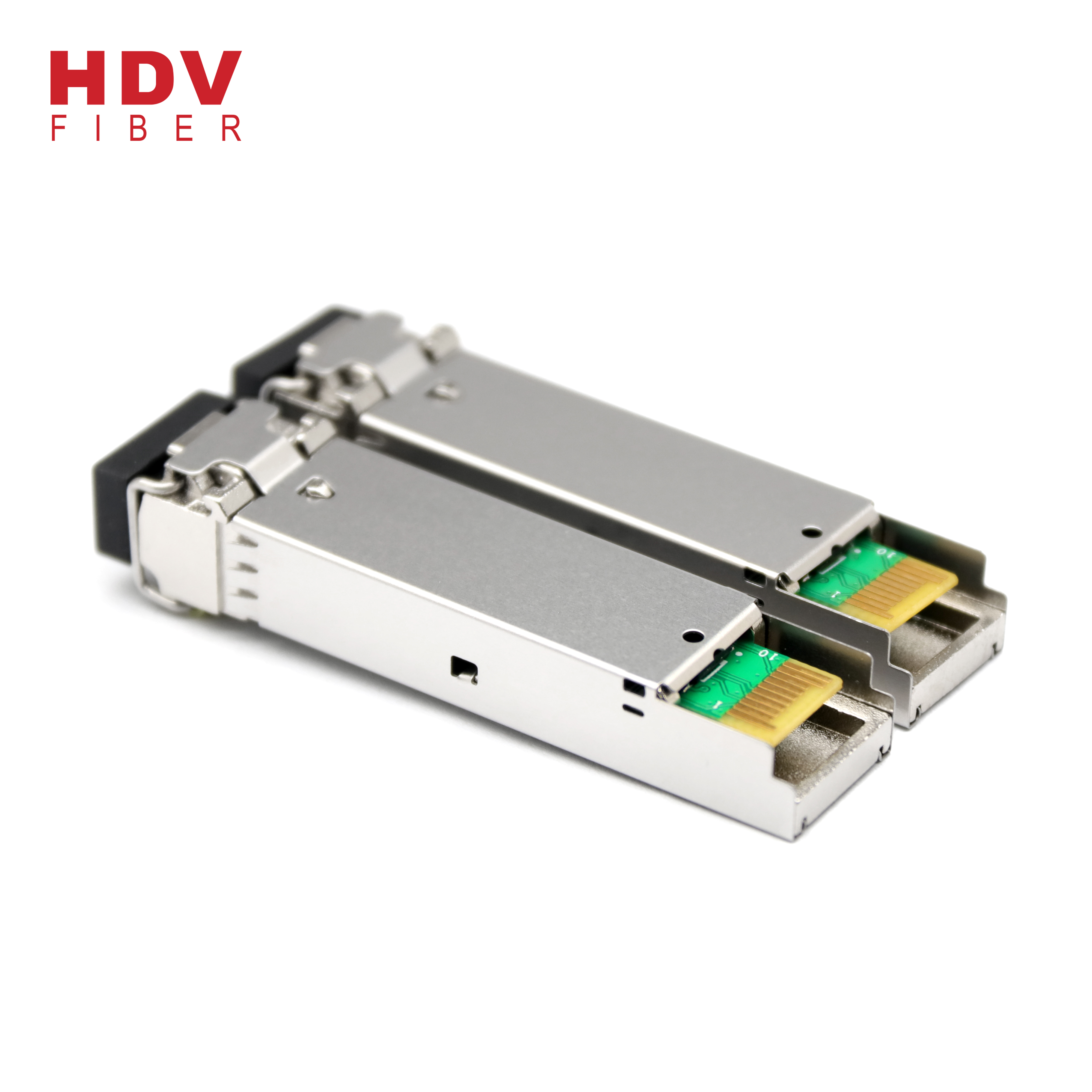
Pin Assignment:
|
Pin |
Descriptions |
Pin |
Descriptions |
|
1 |
VEET |
Transmitter Ground (Common with Receiver Ground) |
1 |
|
2 |
TFAULT |
Transmitter Fault. |
2 |
|
3 |
TDIS |
Transmitter Disable. Laser output disabled on high or open. |
3 |
|
4 |
MOD_DEF(2) |
Module Definition 2. Data line for Serial ID. |
4 |
|
5 |
MOD_DEF(1) |
Module Definition 1. Clock line for Serial ID. |
4 |
|
6 |
MOD_DEF(0) |
Module Definition 0. Grounded within the module. |
4 |
|
7 |
Rate Select |
No connection required |
|
|
8 |
LOS |
Loss of Signal indication. Logic 0 indicates normal operation. |
5 |
|
9 |
VEER |
Receiver Ground (Common with Transmitter Ground) |
1 |
|
10 |
VEER |
Receiver Ground (Common with Transmitter Ground) |
1 |
|
11 |
VEER |
Receiver Ground (Common with Transmitter Ground) |
1 |
|
12 |
RD- |
Receiver Inverted DATA out. AC Coupled |
|
|
13 |
RD+ |
Receiver Non-inverted DATA out. AC Coupled |
|
|
14 |
VEER |
Receiver Ground (Common with Transmitter Ground) |
1 |
|
15 |
VCCR |
Receiver Power Supply |
|
|
16 |
VCCT |
Transmitter Power Supply |
|
|
17 |
VEET |
Transmitter Ground (Common with Receiver Ground) |
1 |
|
18 |
TD+ |
Transmitter Non-Inverted DATA in. AC Coupled. |
|
|
19 |
TD- |
Transmitter Inverted DATA in. AC Coupled. |
|
|
20 |
VEET |
Transmitter Ground (Common with Receiver Ground) |
1 |
Notes:
1. Circuit ground is internally isolated from chassis ground.
2. TFAULTis an open collector/drain output, which should be pulled up with a 4.7k – 10k Ohms resistor on the host board if intended
2. TFAULTis an open collector/drain output, which should be pulled up with a 4.7k – 10k Ohms resistor on the host board if intended
for use. Pull up voltage should be between 2.0V to Vcc + 0.3V. A high output indicates a transmitter fault caused by either the TX bias
current or the TX output power exceeding the preset alarm thresholds. A low output indicates normal operation. In the low state, the
output is pulled to 2.0V or open, enabled on TDIS<0.8V.
4. Should be pulled up with 4.7k – 10 kohms on host board to a voltage between 2.0V and 3.6V.
output is pulled to 2.0V or open, enabled on TDIS<0.8V.
4. Should be pulled up with 4.7k – 10 kohms on host board to a voltage between 2.0V and 3.6V.
MOD_DEF(0) pulls line low to indicate module is plugged in.
5. LOS is open collector output. Should be pulled up with 4.7k – 10 kohms on host board to a voltage between 2.0V and 3.6V. Logic 0
5. LOS is open collector output. Should be pulled up with 4.7k – 10 kohms on host board to a voltage between 2.0V and 3.6V. Logic 0
indicates normal operation; logic 1 indicates loss of signal.
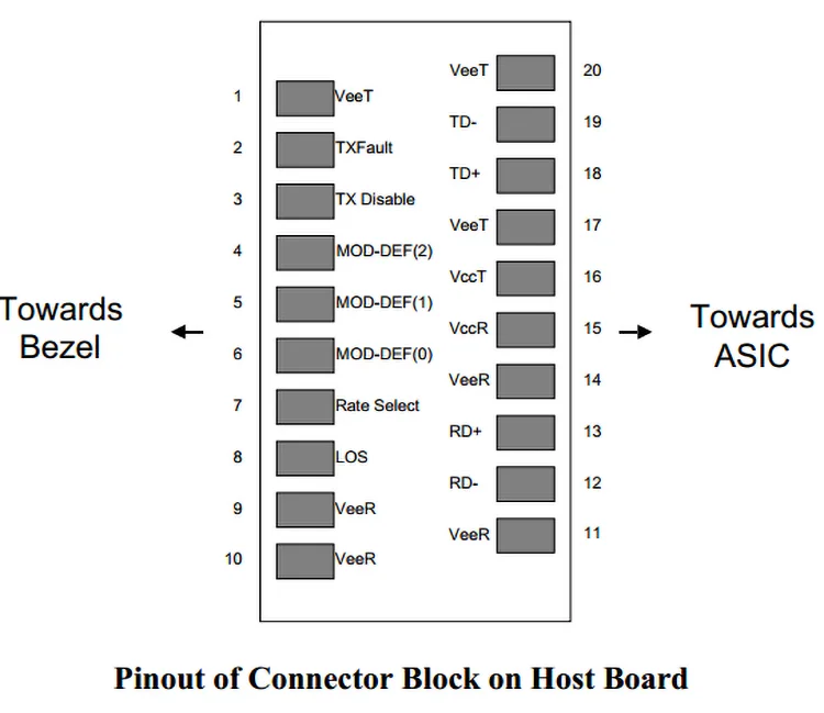
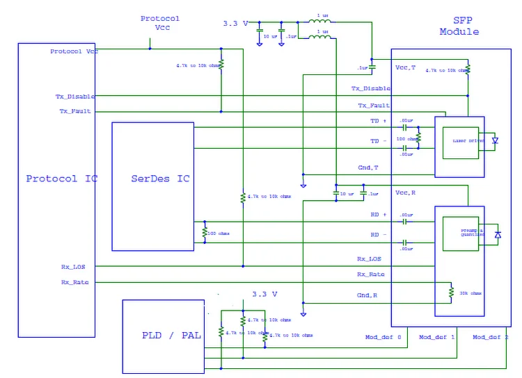
Figure 2 Example SFP Host Board Schematic
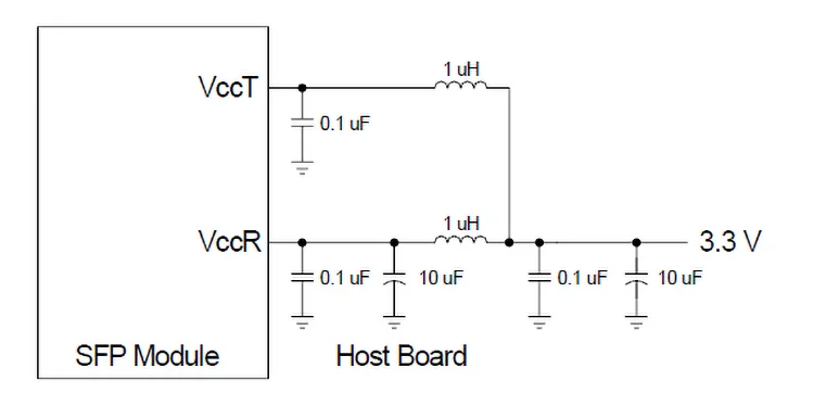
Figure 3 Recommended Host Board Supply Filtering Network
Small Form-factor Pluggable (SFP) Transceiver MultiSource Agreement (MSA)
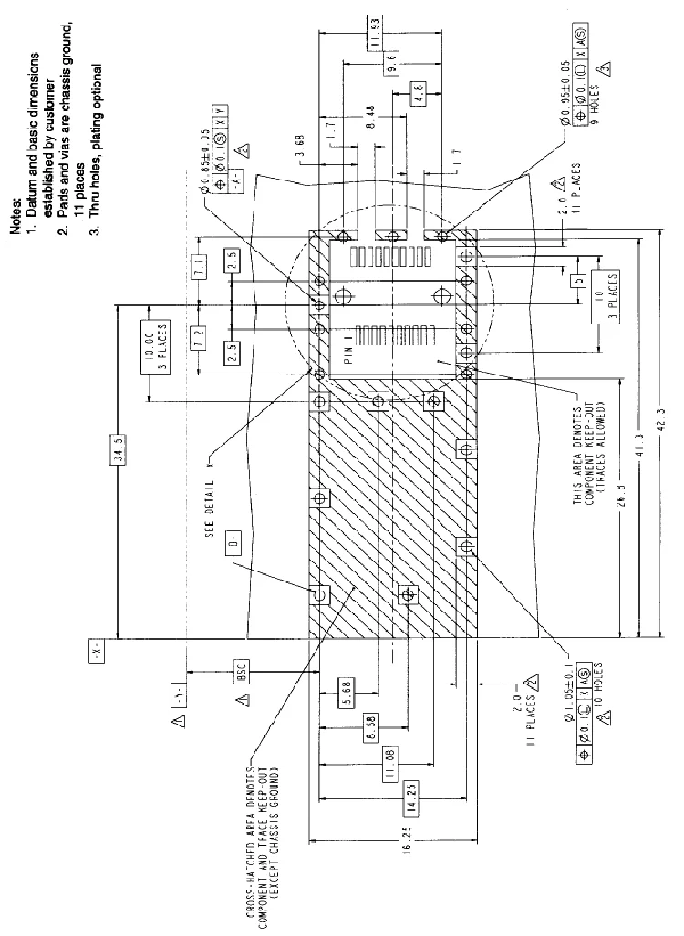
Figure 4 SFP Host Board Mechanical Layout
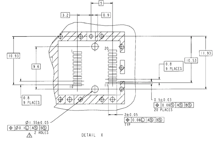
Figure 5 SFP Host Board Mechanical Layout (Cont.)
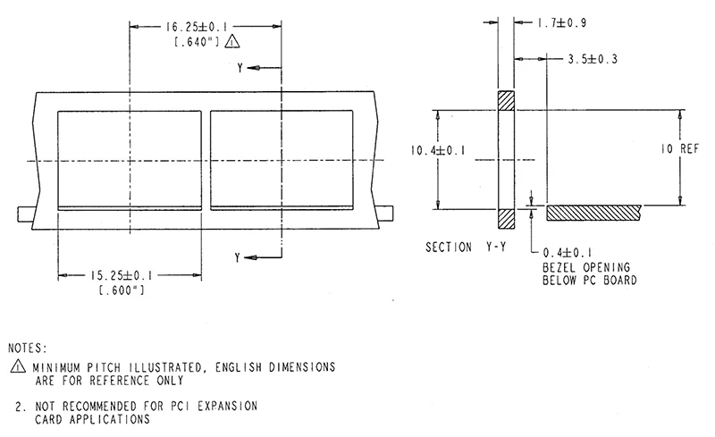
Figure 6 Recommended Bezel Design
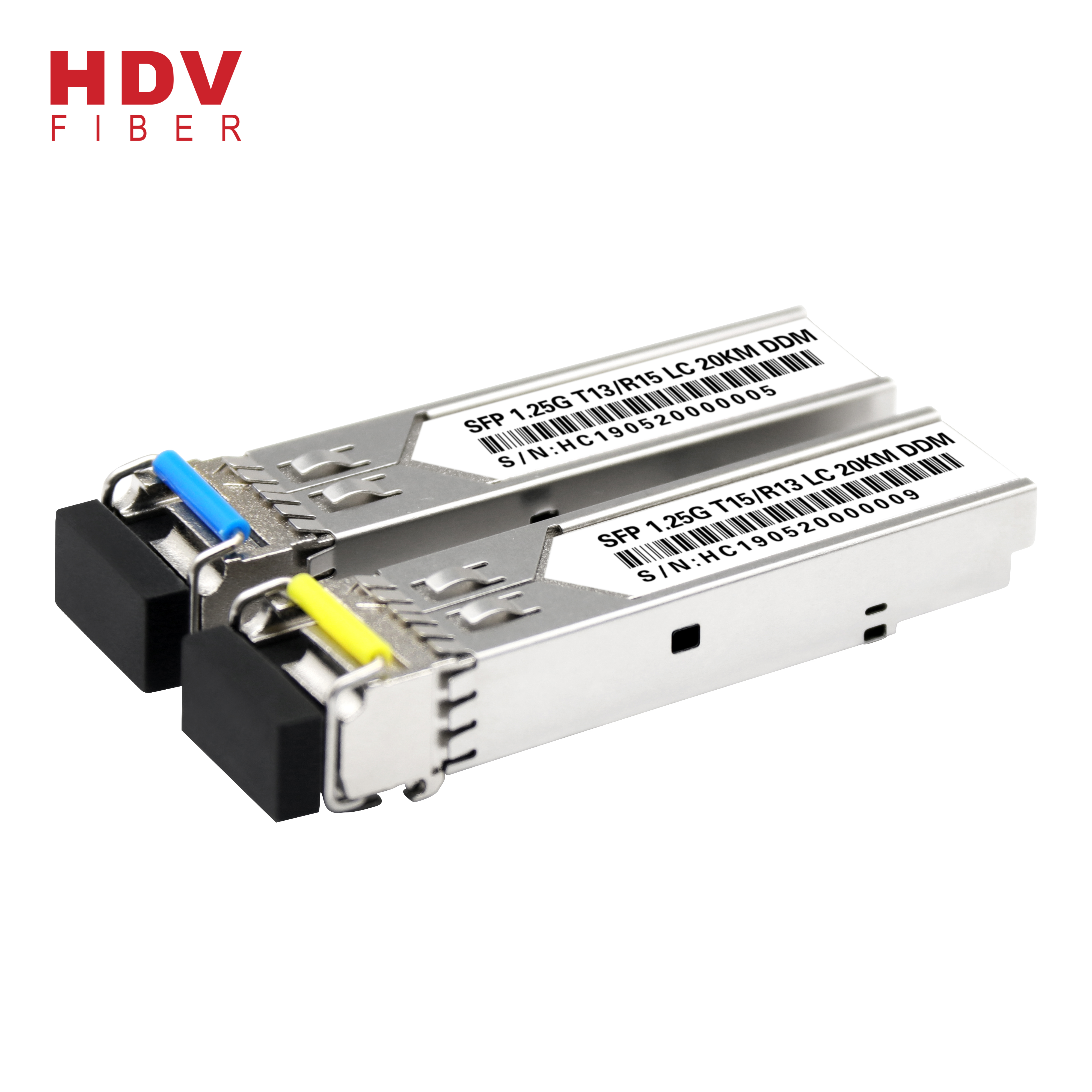
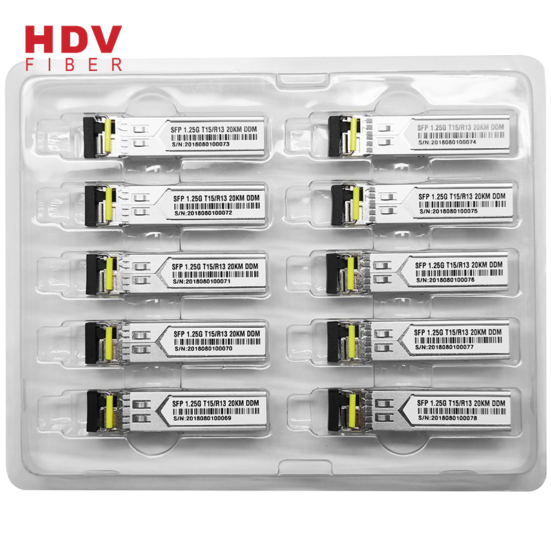
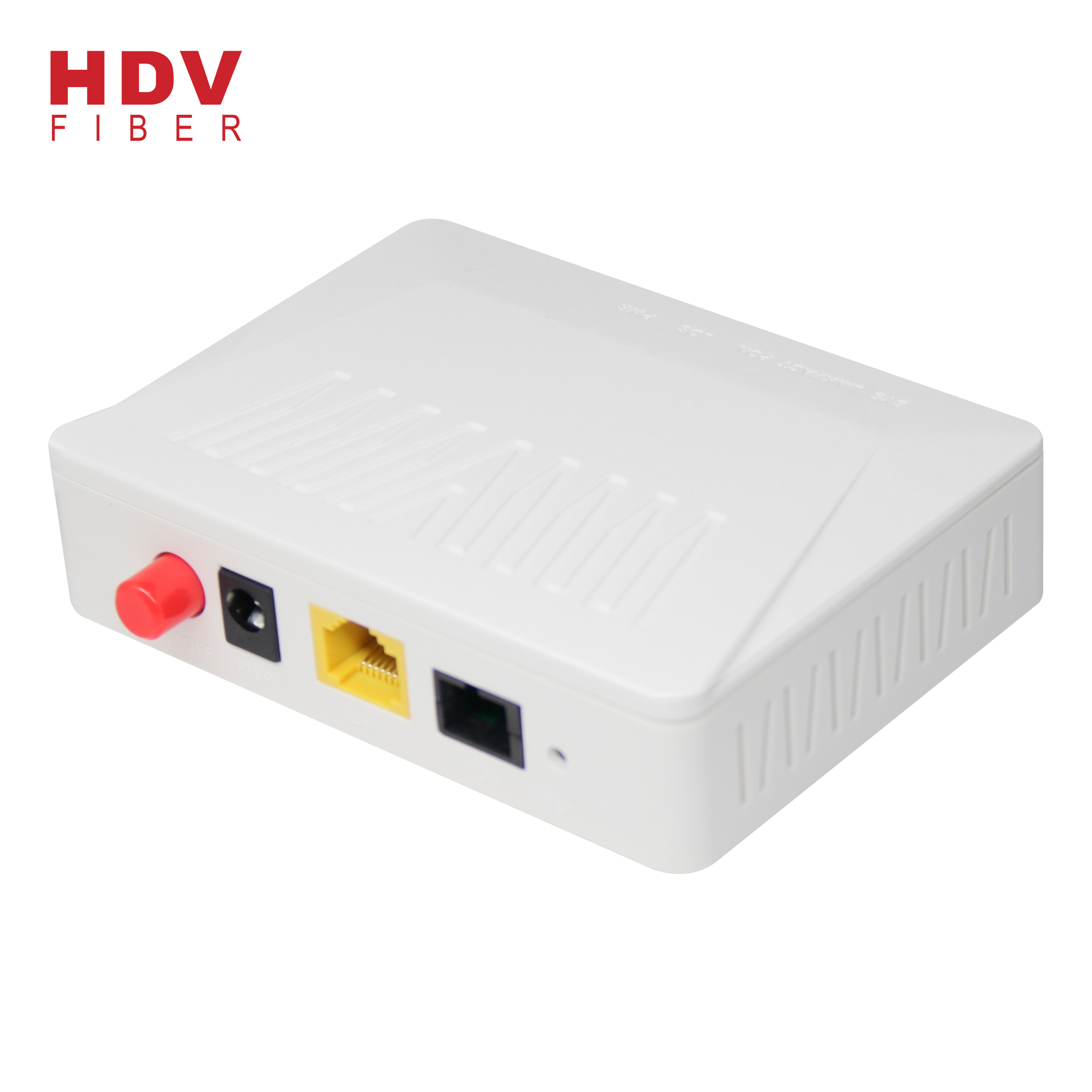
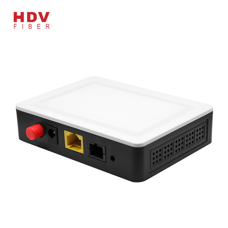
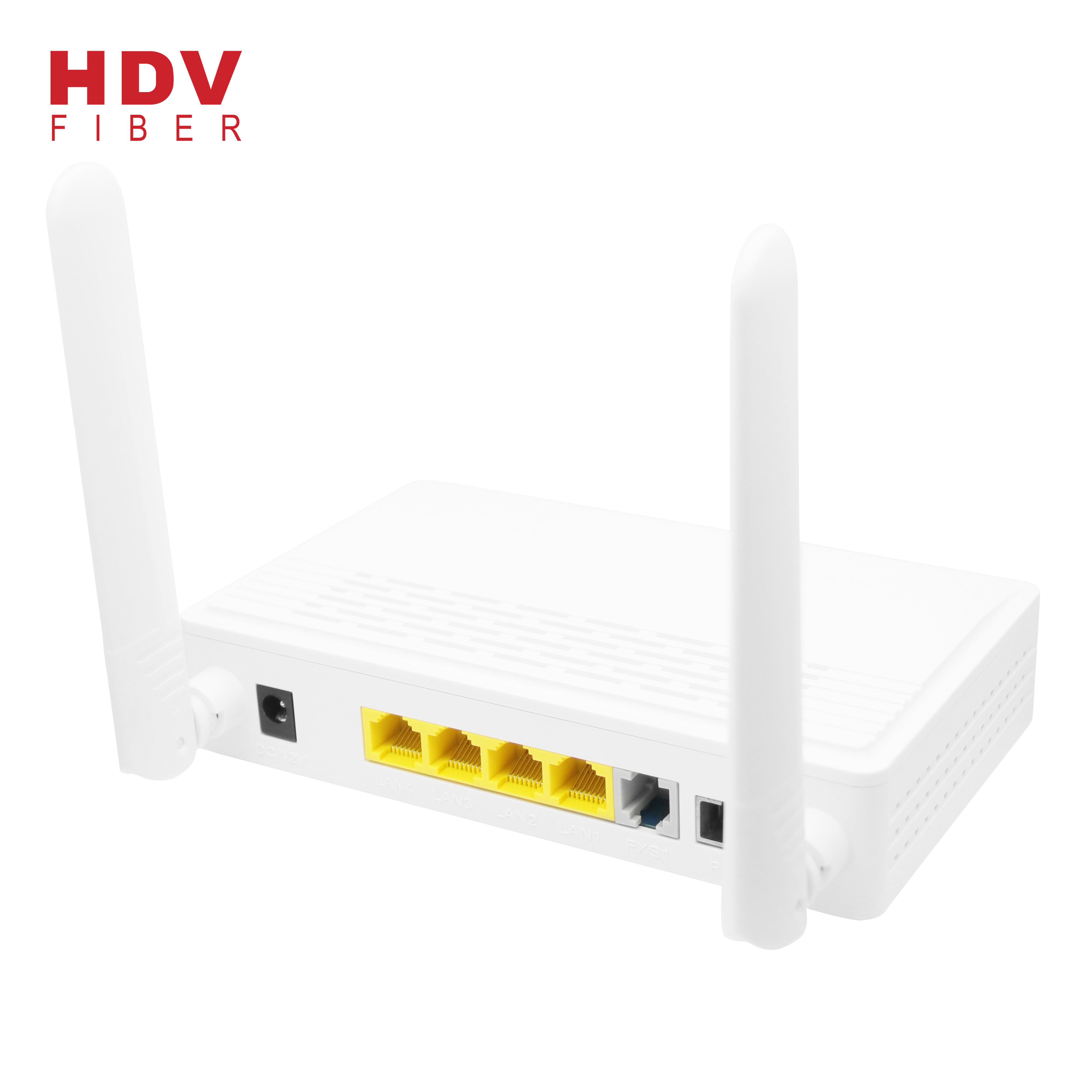
Product detail pictures:

Related Product Guide:
EFFECT Photonics closes Series B funding round | Sfp Gpon Onu
Juniper Networks lays out silicon photonics based pluggable optical module plans | Second Hand Onu
owing to fantastic assistance, a variety of high quality goods, aggressive rates and efficient delivery, we love a very good popularity among our customers. We are an energetic firm with wide market for Good User Reputation for Sfp Module 1.25 - 20km Single Mode Lc Connector 1.25g Single Fiber Sfp Transceiver Optic Module – HDV , The product will supply to all over the world, such as: Belgium, Cairo, Slovak Republic, The development of our company not only needs the guarantee of quality, reasonable price and perfect service, but also relies on our customer's trust and support! In the future, we will continue with the most professional and high quality service to provide the most competitive price, Together with our customers and achieve win-win! Welcome to inquiry and consult!
This supplier offers high quality but low price products, it is really a nice manufacturer and business partner.
Products categories
Write your message here and send it to us