


Notes:
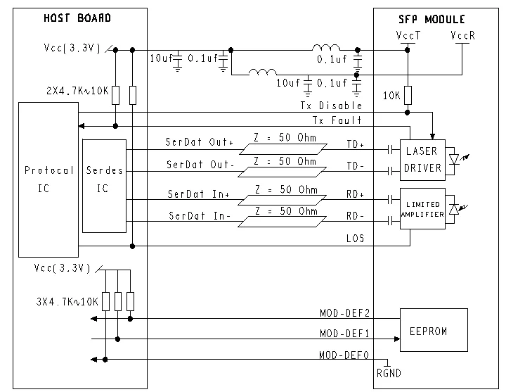
1. TX Fault is an open collector output, which should be pulled up with a 4.7k~10kΩ resistor on the host board to a voltage
between2.0V and Vcc+0.3V. Logic 0 indicates normal operation; logic 1 indicates a laser fault of some kind. In the low state,
the output will be pulled to less than 0.8V.
2. TX Disable is an input that is used to shut down the transmitter optical output. It is pulled up within themodule
witha 4.7k~10kΩ resistor. Its states are:
Low (0~0.8V): Transmitter on
(>0.8V, <2.0V): Undefined
High (2.0~3.465V): Transmitter Disabled
Open: Transmitter Disabled
3. MOD-DEF 0,1,2 are the module definition pins. They should be pulled up with a 4.7k~10kΩ resistor on
the host board. The pull-up voltage shall be VccT or VccR.
MOD-DEF 0 is grounded by the module to indicate that the module is present
MOD-DEF 1 is the clock line of two wire serial interface for serial ID
MOD-DEF 2 is the data line of two wire serial interface for serial ID
4. LOS is an open collector output, which should be pulled up with a 4.7k~10kΩ resistor on the host board to a voltage
between2.0Vand Vcc+0.3V. Logic 0 indicates normal operation; logic 1 indicates loss of signal. In the low state, the
output will be pulled to less than 0.8V.
5. These are the differential receiver output. They are internally AC-coupled 100Ω differential lines which should be terminated
with 100Ω (differential) at the user SERDES.
6. These are the differential transmitter inputs. They are AC-coupled, differential lines with 100Ω differential termination inside the module.
6. These are the differential transmitter inputs. They are AC-coupled, differential lines with 100Ω differential termination inside the module.
Recommended Application Circuit:
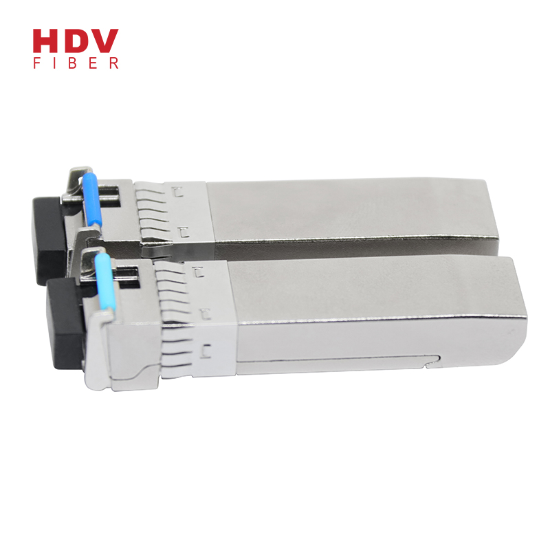
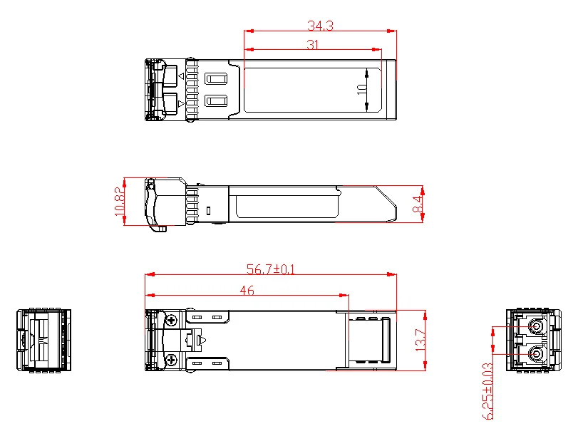
Outline drawing (mm):
Ordering information :
|
Part No. |
Wavelength |
Connector |
Temp. |
TX Power (dBm) |
RX Sens (Max.) (dBm) |
Distance |
|
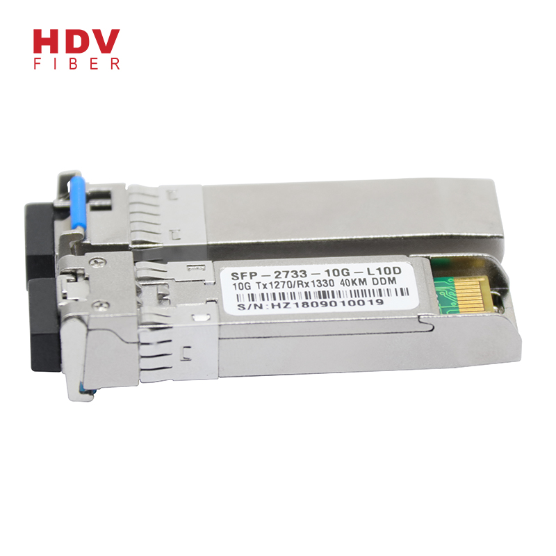
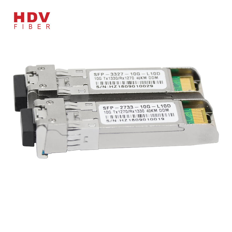
BSFP+-10G-L10A |
1270TX/1330RX |
LC |
0~70°C |
-5 to 0 |
-14 |
10km |
|
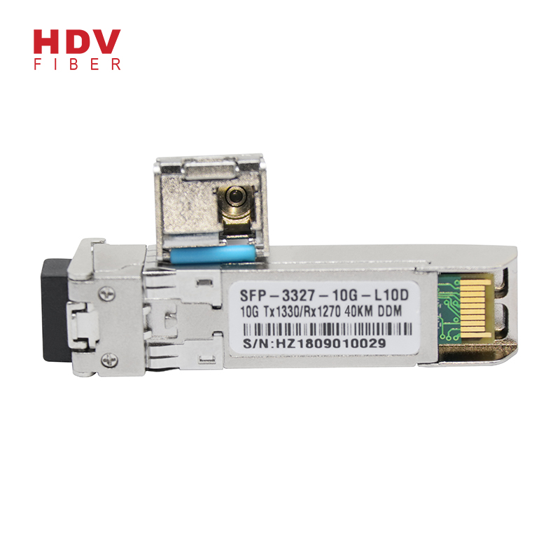
BSFP+-10G-L10B |
1330TX/1270RX |
LC |
0~70°C |
-5 to 0 |
-14 |
10km |
|
BSFP+-10G-L20A |
1270TX/1330RX |
LC |
0~70°C |
-2to 3 |
-14 |
20km |
|
BSFP+-10G-L20B |
1330TX/1270RX |
LC |
0~70°C |
-2to 3 |
-14 |
20km |
|
BSFP+-10G-L40A |
1270TX/1330RX |
LC |
0~70°C |
+1 to +5 |
-17 |
40km |
|
BSFP+-10G-L40B |
1330TX/1270RX |
LC |
0~70°C |
+1 to +5 |
-17 |
40km |
|
BSFP+-10G-L60A |
1270TX/1330RX |
LC |
0~70°C |
+1 to +6 |
-20 |
60km |
|
BSFP+-10G-L60B |
1330TX/1270RX |
LC |
0~70°C |
+1 to +6 |
-20 |
60km |
Products categories
-
Huawei/cisco Compatible 10g Sfp+ lr 10km 10g Sf...
-
10g bidi sfp 10km 1330 1270 optical fiber trans...
-

Reliable and stable 10g sfp module 60km bidi 12...
-
10G 1310nm 20KM LC connector dual fiber optic S...
-
SFP 10G bidi 1270nm/1330nm optical fiber transc...
-
10G 1550nm 40KM LC connector dual fiber optic S...
Write your message here and send it to us