


● Complies with SFP Multi-Source Agreement (MSA) SFF-8074i
● Complies with ITUT-T G.984.2, G.984.2 Amendment 1
● Complies with ITUT G.988 ONU management and control interface (OMCI) specification
● Complies with SFF 8472 V9.5
● Complies with FCC 47 CFR Part 15, Class B
● Complies with FDA 21 CFR 1040.10 and 1040.11
The HTR6001X series transceiver is a high performance module for single fiber
communications using a 1310nm burst- mode transmitter and a 1490nm continuous-mode
receiver. It is used in the optical network terminal (ONT) for GPON ONU Class B+ applications
with Mac inside.
The Transmitter is designed for single mode fiber and operates at a nominal wavelength
of 1310nm. The transmitter module uses a DFB laser diode with full IEC825 and CDRH class 1
eye safety.
The receiver section uses a hermetic packaged APD-TIA (APD with trans-impedance amplifier) and
a limiting amplifier. The APD converts optical power into electrical current and the current is
V1.0 page 2 of 10
transformed to voltage by the trans-impedance amplifier. The differential DATA and /DATA CML data
signals are produced by the limiting amplifier.
An enhanced Digital Diagnostic Monitoring Interface has been incorporated into the
transceivers. It allows real time access to the transceiver operating parameters such as transceiver
temperature, laser bias current, burst mode transmitted optical power, received optical power and
transceiver supply voltage by reading a built-in memory with I2C interface.
● Gigabit-capable Passive Optical Networks (GPON)
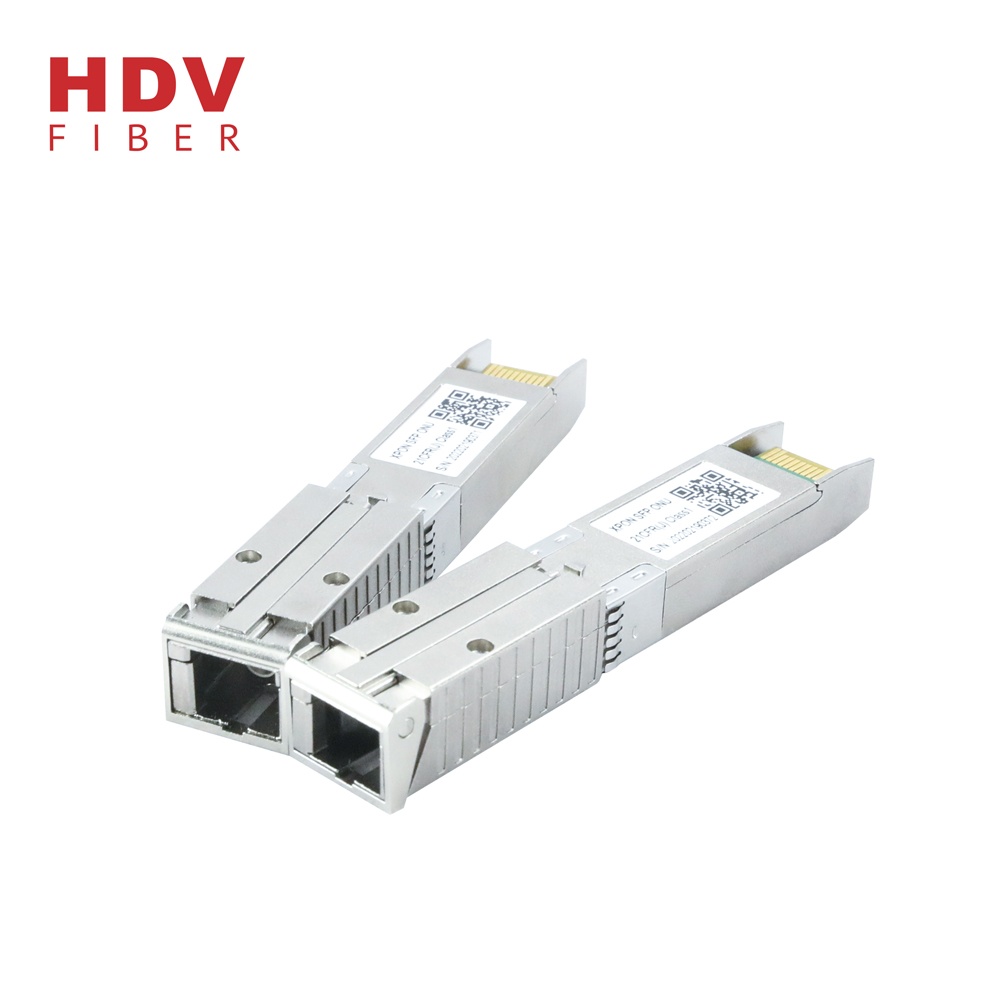
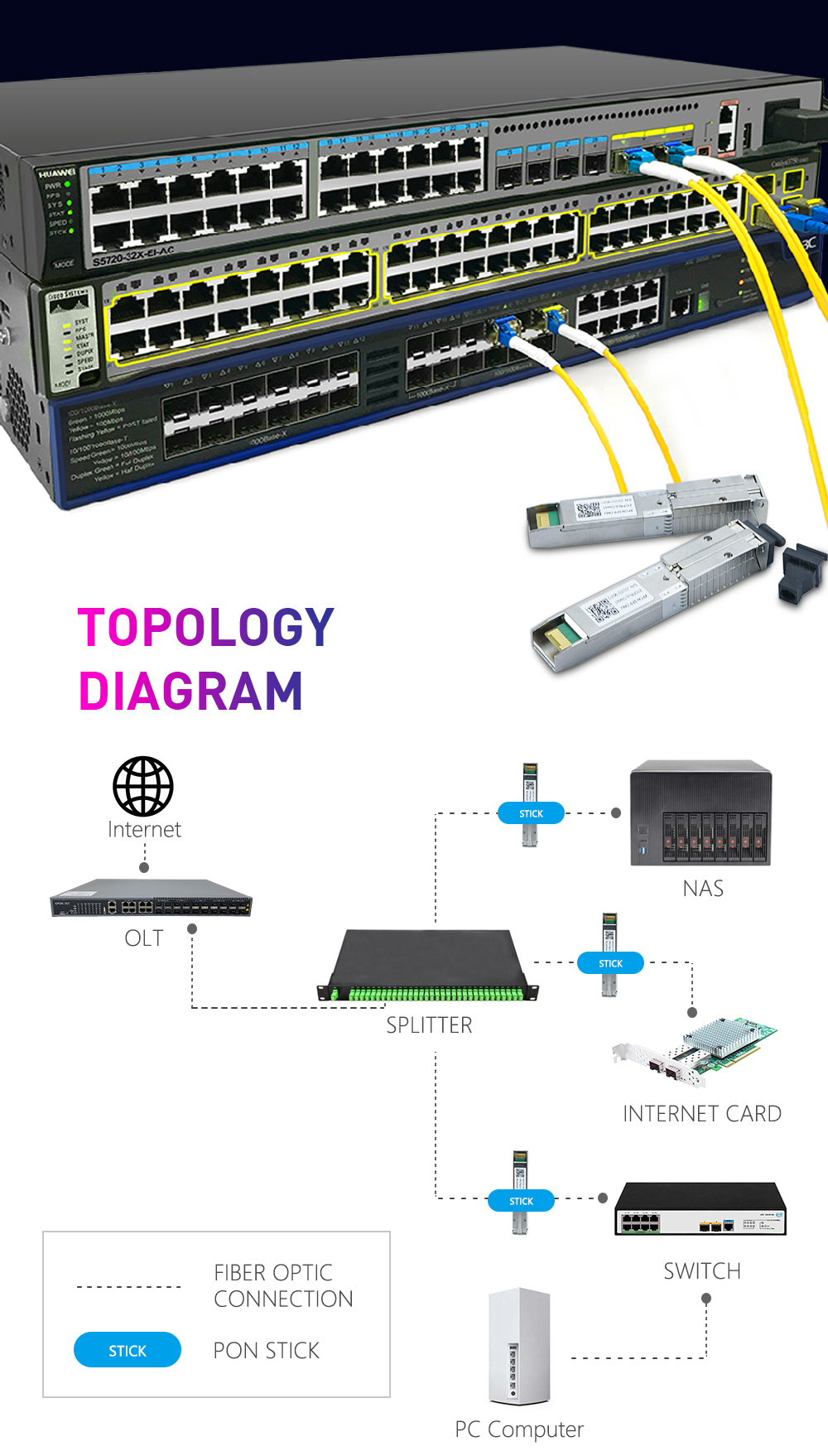
● HTR6001X is a MSA-compliant SFP that incorporates not just the optics for an ONU, but all of
the electronics need as well. It is a “PON on a Stick” that an entire FTTH ONU in a slightly
oversized SFP. It can be plugged into networking equipment. Allowing the data interfaces on a
switch, router, PBX, etc. to be customized for different fiber environments and distance
requirements
● The HTR6001X is designed as dual-mode ONU stick, it also supports the EPON ONU OAM. It
can be applied both on EPON system and on the GPON system .It will automatically establish
an EPON link with the EPON OLT or GPON link with the GPON OLT.
| Parameter | Symbol | Minimum | Maxim | Unit | Note |
| Storage Ambient Temperature | TSTG | -40 | 85 | °C | |
| Operating Case Temperature | Tc | 0 | 70 | °C | C-Temp |
| -40 | 85 | °C | I -Temp | ||
| Operating Humidity | OH | 5 | 95 | % | |
| Power Supply Voltage | VCC | 0 | 3.63 | V | |
| Receiver Damaged Threshold | +4 | dBm | |||
| Soldering Temperature | 260/10 | °C/S |
| Parameter | Symbol | Minimum | Typical | Maxim |
Unit |
Note |
| Power Supply Voltage | VCC | 3.13 | 3.3 | 3.47 | V |
3.3V±5% |
| Power Dissipation | PD | 2.00 | 2.48 | W | ||
| Operating Case Temperature | Tc | 0 | 70 | °C |
C-Temp |
|
| -40 | 85 | °C |
I -Temp |
|||
| Operating Humidity Range | OH | 5 | 85 | % | ||
| Data Rate upstream | 1.244 |
Gbit/s |
||||
| Data Rate downstream | 2.488 |
Gbit/s |
||||
| Data Rate Drift | -100 | +100 |
PPM |
| Parameter |
Symbo |
Minimu | Typical | Maxim | Unit | Note |
| Optical Center Wavelength | λC | 1290 | 1330 | nm | ||
| Side Mode Suppression Ratio |
SMSR |
30 | dB | |||
| Optical Spectrum Width | ∆λ | 1 | nm | |||
| Average Launch Optical Power | Po | +0.5 | +5 | dBm | 1 | |
| Power-OFF Transmitter Optical | Poff | -45 | dBm | |||
| Extinction Ratio | ER | 9 | dB | 2 | ||
| Rise/Fall Time (20%-80%) | TR/TF | 260 | ps | 2,3 | ||
| Turn On Time at Burst mode | Ton | 12.8 | ns | |||
| Turn Off Time at Burst mode | Toff | 12.8 | ns | |||
| RIN15OMA | -115 | dB/Hz | ||||
| Optical Return Loss Tolerance | 15 | dB | ||||
| Transmitter Reflectance | -6 | dB | ||||
| Transmitter and Dispersion Penalty | TDP | 2 | dB | 4 | ||
| Optical Waveform Diagram | Compliant With ITU-T G.984.2 | 5 | ||||
| Data Input Differential Swing | 300 | 1600 | mV | 6 | ||
| Input Differential Impedance | 90 | 100 | 110 | Ω | ||
| Tx-Disable Voltage (Enable) | 0 | 0.8 | V | |||
| Tx-Disable Voltage (Disable) | 2.0 | VCC | V | |||
| Tx-Fault Output (Normal) | 0 | 0.8 | V | |||
| Tx-Fault Output (Fault) | 2.0 | VCC | V | |||
Note 1: Launched into 9/125um Single Mode Fiber.
Note 2: Measured with PRBS 223-1 test pattern @1.244Gbit/s. Note 3: Measured with the Bessel-Thompson filter OFF.
Note 4: Maximum sensitivity penalty due to transmitter and dispersion effect through 20km of SMF optical fiber. Note 5: Transmitter eye mask definitions (Figure 1).
Note 6: Compatible with LVPECL input, DC coupled internally.
Figure 1 Transmitter Eye Mask Definiti
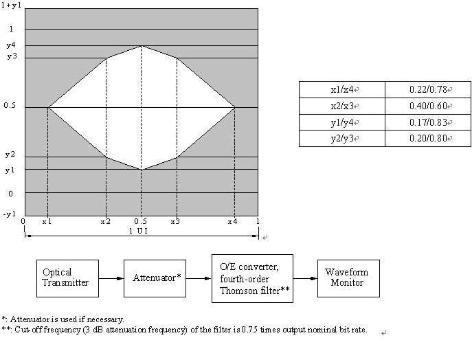
Figure 1 Transmitter Eye Mask Definitions
| Parameter | Symbol | Minimu | Typical | Maxim | Unit | Notes |
| Operating Wavelength | 1480 | 1490 | 1500 | nm | ||
| Sensitivity | SEN | -28 | dBm | |||
| Saturation Optical Power | SAT | -8 | dBm | 1 | ||
| LOS Deassert Level | -29 | dBm | ||||
| LOS Assert Level | -40 | dBm | 2 | |||
| LOS Hysteresis | 0.5 | 5 | dB | |||
| Receiver Reflectance | -20 | dB | ||||
| 38 | dB | 1550nm | ||||
| WDM Filter Isolation | 35 | dB | 1650nm | |||
| Data Output Differential Swing | 300 | 1200 | mV | 3 | ||
| LOS low voltage | 0 | 0.8 | V | |||
| LOS high voltage | 2 | VCC | V |
Note 1: Measured with a PRBS 223-1 test pattern @2.488Gbit/s and ER=9dB, BER =10-12.
Note 2: A decrease in optical power above the specified level will cause Los output to switch from a low state to a high state;
An increase in optical power below the specified level will cause Los output to switch from a high state to a low state.
Note 3: CML output, AC coupled internally, guaranteed in the full range of input optical power (-8dBm to -28dBm).
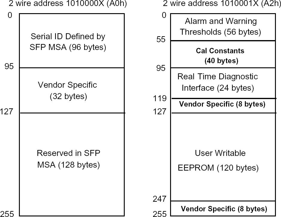
Figure 2 EEPROM Information

Figure 3 Package Outline (unit: mm)
| PIN | Name | Description | Notes |
| 1 | VeeT | Transmitter Ground | 1 |
| 2 | Tx-Fault | Transmitter Fault Indication ,Normal “0”,fault:Logic “1”output , LVTTL | 2 |
| 3 | Tx-Disable | Transmitter Disable; turns off transmitter laser | 3 |
| 4 | Mod-Def(2) | SDA I2C Data line | 2 |
| 5 | Mod-Def(1) | SCL I2C Clock line | 2 |
| 6 | Mod-Def(0) | Module Absent, connected to VeeR | 2 |
| 7 | Rate Select | For Dying Gasp detect, input low active | |
| 8 | LOS | Loss of Signal | 2 |
| 9 | VeeR | Receiver Ground | 1 |
| 10 | VeeR | Receiver Ground | 1 |
| PIN | Name | Description | Notes |
| 11 | VeeR | Receiver Ground | 1 |
| 12 | RD- | Inv. Received Data Output | |
| 13 | RD+ | Received Data Output | |
| 14 | VeeR | Receiver Ground | 1 |
| 15 | VccR | Receiver Power | 1 |
| 16 | VccT | Transmitter Power | |
| 17 | VeeT | Transmitter Ground | 1 |
| 18 | TD+ | Transmit Data In | |
| 19 | TD- | Inv.Transmit Data In | |
| 20 | VeeT | Transmitter Ground | 1 |
Notes:
1. Module circuit ground is isolated from module chassis ground within the module.
2. The pins shall be pulled up with 4.7K-10KΩ to a voltage between 3.13V and 3.47V on host board.
3. The pin is pulled up to VccT with a 4.7K-10KΩ resistor in the module.
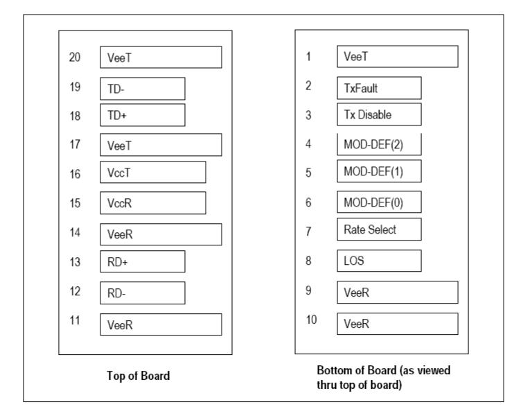
Figure 4 Pin Out Drawing (Top view)
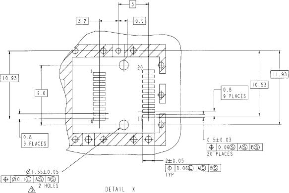
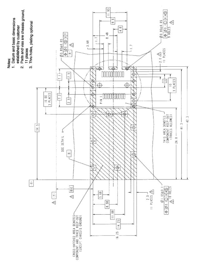
Figure 5 Recommended Board Layout Hole Pattern and Panel Mounting
Products categories


Write your message here and send it to us